1. 什么是 GoBGP?
GoBGP 是使用 Go 语言开发的,运行在 Linux 系统上的开源工具,可以提供 BGP 协议的控制平面功能。与 Guagga/FRRouting 相比,GoBGP 的性能更好,收敛时间更短,可以适用于更大规模的网络,比如充当 IXP 路由器:
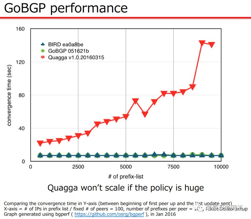
GoBGP 仅支持 BGP 这一种路由协议,但是它可以和 Zebra 集成,通过 API 的方式与 Guagga/FRR 协同工作,以支持多种路由协议。
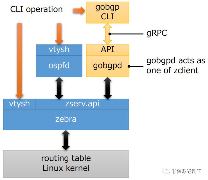
可以使用 Python、C++ 等多种语言,通过 gRPC API 对 GoBGP 进行配置,当然也支持 CLI。GoBGP 还支持 OpenConfig,其 YANG 模型符合 draft-ietf-idr-bgp-model-03。
因为 GoBGP 可以很方便地人工干涉路由,参与感更强,是一个很好的实验工具。本文就利用 GoBGP 和 Cisco NXOSv 搭建实验环境,来学习 VXLAN EVPN 的一些原理。
2. 安装 GoBGP
GoBGP 的安装非常简单,从 https://github.com/osrg/gobgp/releases 下载 tar.gz 文件,解压即可。在元旦之前(注:2019年元旦),GoBGP 刚刚 Release 了 v2.0.0。
$ tar -xzf gobgp_2.0.0_linux_amd64.tar.gz
解压之后可以看到 2 个可执行文件:gobgp
和 gobgpd
。其中 gobgp
是 gRPC 的 CLI client 工具, gobgpd
是 GoBGP 主程序。
$ ls -l
total 40740
-rwxrwxr-x. 1 chengc2 chengc2 14386512 Dec 30 05:17 gobgp
-rw-rw-r--. 1 chengc2 chengc2 11299444 Jan 12 23:13 gobgp_2.0.0_linux_amd64.tar.gz
-rwxrwxr-x. 1 chengc2 chengc2 16005264 Dec 30 05:18 gobgpd
-rw-rw-r--. 1 chengc2 chengc2    11324 Jun  8  2017 LICENSE
-rw-rw-r--. 1 chengc2 chengc2     2412 Dec 24 01:14 README.md
如果使用源代码方式安装,可以获取最新的 master branch,但是要复杂一些。
首先安装 Golang。从 https://golang.org/dl 下载 binary release,需要 1.11 或更高版本,解压到 usr/local 目录:
$ sudo tar -C /usr/local -xzf go1.11.4.linux-amd64.tar.gz
然后设置环境变量:
# Ubuntu修改$HOME/.profile
$ sudo vi $HOME/.profile

# CentOS修改/etc/profile
$ sudo vi /etc/profile

# 在profile文件底部增加2行:
export GOPATH=$HOME/go
export PATH=$PATH:/usr/local/go/bin

$ mkdir $HOME/go

# Ubuntu使profile立即生效:
$ source $HOME/.profile

# CentOS使profile立即生效:
$ source /etc/profile
最后 goget
两个 binary 文件:
$ go get github.com/osrg/gobgp/gobgp
$ go get github.com/osrg/gobgp/gobgpd
如果无法直接访问境外的服务器,源代码安装很容易失败。所以还是建议使用 binary release。
3. 准备 Cisco 网络环境
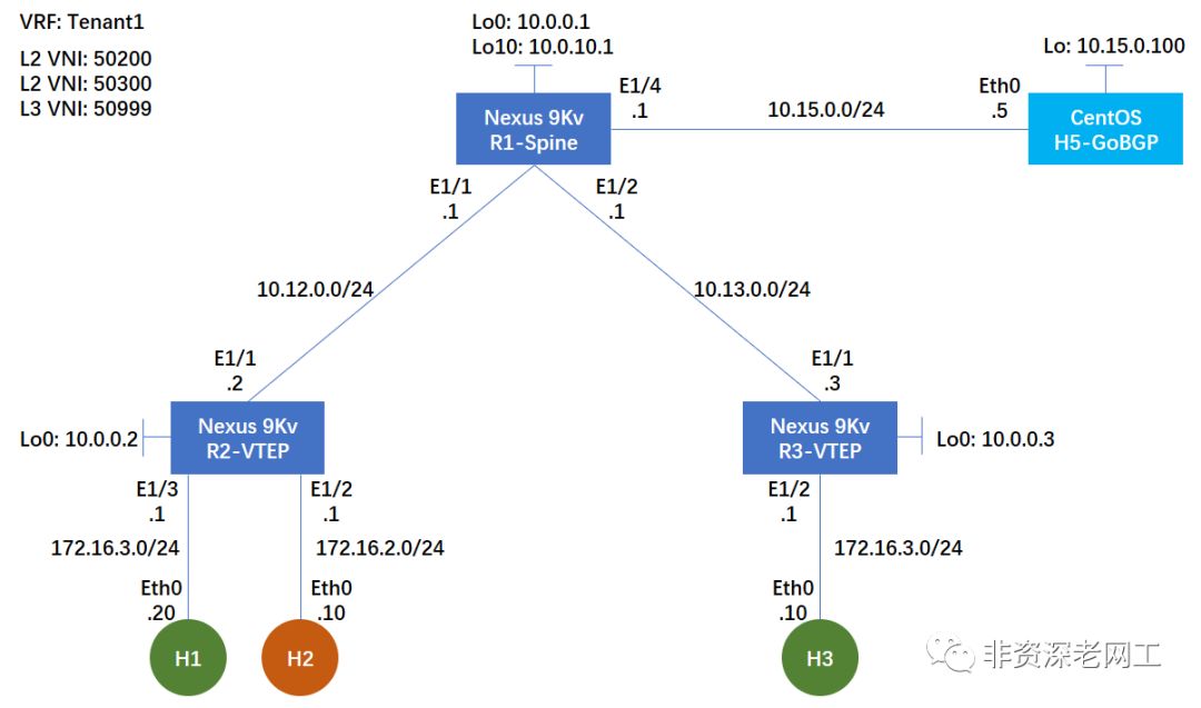
在继续实验之前,先按照下面的拓扑准备好 Cisco 的网络环境。本次实验采用 iBGP,仅配置 l2vpn evpn
address-family。
3.1 R1-Spine 设备配置
# 开启相关feature
nv overlay evpn
feature ospf
feature bgp
feature pim
feature vn-segment-vlan-based
feature nv overlay

# 配置Rendezvous Point
ip pim rp-address 10.0.10.1 group-list 224.0.0.0/4
ip pim ssm range 232.0.0.0/8

interface Ethernet1/1
  description to R2
  mtu 9000                            # ESXi Standard Switch的MTU最大9000
  mac-address 000c.2915.3243        # NXOSv需要手工配置L3接口MAC
  ip address 10.12.0.1/24
  ip ospf network point-to-point
  ip router ospf 1 area 0.0.0.0
  ip pim sparse-mode
  no shutdown

interface Ethernet1/2
  description to R3
  mtu 9000
  mac-address 000c.2915.3244
  ip address 10.13.0.1/24
  ip ospf network point-to-point
  ip router ospf 1 area 0.0.0.0
  ip pim sparse-mode
  no shutdown

interface Ethernet1/4
  description to H5-GoBGP
  mtu 9000
  mac-address 000c.2915.3246
  ip address 10.15.0.1/24
  ip router ospf 1 area 0.0.0.0
  ip pim sparse-mode
  no shutdown

interface loopback0
  ip address 10.0.0.1/32
  ip router ospf 1 area 0.0.0.0
  ip pim sparse-mode

interface loopback10
  description PIM-RP                # 也可以用Loopback0作为RP
  ip address 10.0.10.1/32
  ip router ospf 1 area 0.0.0.0
  ip pim sparse-mode

router ospf 1
  router-id 10.0.0.1
router bgp 65000
  router-id 10.0.0.1
  template peer LEAF                # 配置peer模板
    remote-as 65000
    update-source loopback0
    address-family l2vpn evpn       # 本次实验不需要配置 IPv4 AF
      send-community
      send-community extended
      route-reflector-client        # 启用RR
  neighbor 10.0.0.2
    inherit peer LEAF                # 让peer继承模板
  neighbor 10.0.0.3
    inherit peer LEAF
  neighbor 10.15.0.100
    inherit peer LEAF
3.2 R2-VTEP & R3-VTEP 设备配置
nv overlay evpn
feature ospf
feature bgp
feature pim
feature interface-vlan
feature vn-segment-vlan-based
feature nv overlay

fabric forwarding anycast-gateway-mac 0001.0001.0001    # 为Anycast GW配置MAC地址
ip pim rp-address 10.0.10.1 group-list 224.0.0.0/4
ip pim ssm range 232.0.0.0/8
vlan 1,200,300,999          # 本次实验为R3-VTEP配置3个不同的VLAN:vlan 1,288,388,888
vlan 200                    # R3-VTEP为vlan 288
  name L2-VNI-50200-Tenant1
  vn-segment 50200          # 将VNI和VLAN绑定
vlan 300                    # R3-VTEP为vlan 388
  name L2-VNI-50300-Tenant1
  vn-segment 50300
vlan 999                    # R3-VTEP为vlan 888
  name L3-VNI-50999-Tenant1
  vn-segment 50999

#因为GoBGP+Cisco异构部署,且需要人工发布路由,所以本次测试采用静态RD和RT
vrf context Tenant1
  vni 50999
  rd 50999:1
  address-family ipv4 unicast
    route-target import 50999:1
    route-target import 50999:1 evpn
    route-target export 50999:1
    route-target export 50999:1 evpn

interface Vlan200           # R3-VTEP为vlan 288
  no shutdown
  vrf member Tenant1
  ip address 172.16.2.1/24
  fabric forwarding mode anycast-gateway

interface Vlan300           # R3-VTEP为vlan 388
  no shutdown
  vrf member Tenant1
  ip address 172.16.3.1/24
  fabric forwarding mode anycast-gateway

interface Vlan999           # R3-VTEP为vlan 888
  no shutdown
  vrf member Tenant1
  ip forward

interface nve1
  no shutdown
  host-reachability protocol bgp
  source-interface loopback0
  member vni 50200
    mcast-group 239.0.0.1
  member vni 50300
    mcast-group 239.0.0.1
  member vni 50999 associate-vrf

interface Ethernet1/1
  description to R1
  mtu 9000
  mac-address 000c.2964.0299    # R3-VTEP配置:mac-address 000c.29c7.522e
  ip address 10.12.0.2/24        # R3-VTEP配置:ip address 10.13.0.3/24
  ip ospf network point-to-point
  ip router ospf 1 area 0.0.0.0
  ip pim sparse-mode
  no shutdown

interface Ethernet1/2
  switchport
  switchport access vlan 200    # R3-VTEP配置:switchport access vlan 388
  no shutdown

interface Ethernet1/3           # R3-VTEP没有配置这个接口
  switchport
  switchport access vlan 300
  no shutdown

interface loopback0
  ip address 10.0.0.2/32        # R3-VTEP配置:ip address 10.0.0.3/32
  ip router ospf 1 area 0.0.0.0
  ip pim sparse-mode

router ospf 1
  router-id 10.0.0.2            # R3-VTEP配置:router-id 10.0.0.3
router bgp 65000
  router-id 10.0.0.2            # R3-VTEP配置:router-id 10.0.0.3
  neighbor 10.0.0.1
    remote-as 65000
    update-source loopback0
    address-family l2vpn evpn
      send-community
      send-community extended
  vrf Tenant1
    address-family ipv4 unicast
      advertise l2vpn evpn

#因为GoBGP+Cisco异构部署,且需要人工发布路由,所以本次测试采用静态RD和RT
evpn
  vni 50200 l2
    rd 50200:1
    route-target import 50200:1
    route-target export 50200:1
  vni 50300 l2
    rd 50300:1
    route-target import 50300:1
    route-target export 50300:1
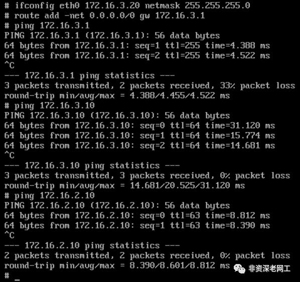
然后用 3 个 Puppy Linux 分别作为 H1,H2 和 H3。从 H2 ping H3,可以 ping 通:
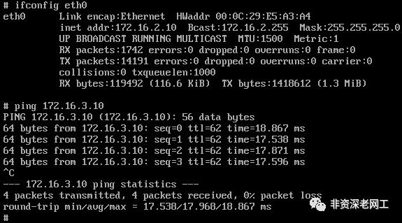
从 H1 ping H3 和 H2,也都可以 ping 通:
4. Symmetric IRB
您应该注意到了,虽然我为 2 个 VTEP R2 和 R3 配置了相同的 L2VNI 和 L3VNI,但是我为它们配置了不同的 VLAN ID。R2 的 3 个 VLAN ID 分别为 200、300、999,而 R3 的 3 个 VLAN ID 分别为 288、388、888。这并不影响 VXLAN 网络的连通性,3 台 Host 都可以互相 ping 通。
draft-ietf-bess-evpn-inter-subnet-forwarding 定义了 2 种 IRB 操作模型,Asymmetric IRB 和 Symmetric IRB,Cisco Nexus 采用的是后一种。在 Symmetric IRB 模型中,Tenant System 1 的流量抵达 Ingress VTEP 之后,先在 Bridge Table 查找 ARP,然后进入 IP-VRF 查找路由表,再封装 L3VNI 传递给 Egress VTEP。流量抵达 Egress VTEP,解封装 L3VNI,在 IP-VRF 查找路由表,然后在 Bridge Table 查找 ARP,最后发给本地的 Tenant System。下图是流量的传输路径:
           Ingress PE                   Egress PE
     +-------------------+        +------------------+
     |                   |        |                  |
     |    +-> IP-VRF ----|---->---|-----> IP-VRF -+  |
     |    |              |        |               |  |
     |   BT1        BT2  |        |  BT3         BT2 |
     |    |              |        |               |  |
     |    ^              |        |               v  |
     |    |              |        |               |  |
     +-------------------+        +------------------+
          ^                                       |
          |                                       |
    TS1->-+                                       +->-TS2
                    图6. Symmetric IRB
现在我们检查一下 VTEP 的 ARP 表:
R2-VTEP# show ip arp vrf Tenant1

...(snip)

IP ARP Table for context Tenant1
Total number of entries: 2
Address         Age       MAC Address     Interface       Flags
172.16.3.20     00:00:48  000c.2996.007a  Vlan300
172.16.2.10     00:00:27  000c.298c.0cfa  Vlan200

R3-VTEP# show ip arp vrf Tenant1

...(snip)

IP ARP Table for context Tenant1
Total number of entries: 1
Address         Age       MAC Address     Interface       Flags
172.16.3.10     00:00:48  000c.2936.0159  Vlan388
在 ARP 表里面有 VLAN ID 的信息,H1 和 H3 虽然位于相同的子网,但是在 R2 和 R3 的 ARP 表中,VLAN ID 并不相同。这并没有关系,因为 ARP 表是本地有效的。
再检查一下 VTEP 的 Bridge 表,请注意第 2 条 entry,这是 H3 的 Bridge 信息。Topology 是本地的 VLAN ID,采用的协议是 BGP 而不是 Local,下一跳是 R3-VTEP 的 IP 而不是本地的接口。这意味着 Intra-Subnet 的流量如果需要跨越不同的 VTEP,也要通过 EVPN 路由。只不过这不涉及到 Symmetric IRB Model,封装的 VNI 是 L2VNI。
R2-VTEP# show l2route evpn mac all

...(snip)

Topology    Mac Address    Prod   Flags         Seq No     Next-Hops
----------- -------------- ------ ------------- ---------- ----------------
200         000c.298c.0cfa Local  L,            0          Eth1/2
300         000c.2936.0159 BGP    SplRcv        0          10.0.0.3
300         000c.2996.007a Local  L,            0          Eth1/3
999         000c.298d.eb0a VXLAN  Rmac          0          10.15.0.100
999         000c.29c7.522d VXLAN  Rmac          0          10.0.0.3
再检查一下 VTEP 的路由表:
R2-VTEP(config-if)# show ip route vrf Tenant1

...(snip)

172.16.3.10/32, ubest/mbest: 1/0
    *via 10.0.0.3%default, [200/0], 01:13:54, bgp-65000, internal, tag 65000 (ev
pn) segid: 50999 tunnelid: 0xa000003 encap: VXLAN

172.16.3.20/32, ubest/mbest: 1/0, attached
    *via 172.16.3.20, Vlan300, [190/0], 00:31:39, hmm
请注意 172.16.3.10/32
这条路由,下一跳是 R3-VTEP,vn-segment(segid)是 50999。如果是 Inter-Subnet 的流量跨越不同的 VTEP,需要通过 EVPN 路由并符合 Symmetric IRB 模型,封装 L3VNI。
无论是 Intra-Subnet 还是 Inter-Subnet,VLAN ID 都是本地有效的。所以在配置 Cisco Nexus 交换机的时候,每一台 VTEP 都可以单独规划 VLAN ID 和 VNI 和 VRF 的 mapping 关系 —— 虽然在 Cisco Nexus 交换机的配置文件中,VNI 必须配置在 VLAN 下面,但这并不意味着整个 Fabric 的 VNI 数量就受限于 VLAN ID 的数量。
5. GoBGP 和 NXOSv 建立 BGP EVPN Neighbor
GoBGP 可以通过 CLI 来建立 Neighbor,也可以采用配置文件的方式。我们先来创建一个名称为 gobgpd.conf
的配置文件:
[global.config]
 as = 65000
 router-id = "10.0.0.5"

[[neighbors]]
  [neighbors.config]
    neighbor-address = "10.0.0.1"
    peer-as = 65000
  [[neighbors.afi-safis]]
    [neighbors.afi-safis.config]
      afi-safi-name = "l2vpn-evpn"
  [neighbors.transport.config]
    local-address = "10.15.0.100"
其中 10.15.0.100 是 H5 的 lo 接口地址。如果不采用 Loopback 接口建立 Neighbor,则不需要在配置文件中写入 neighbors.transport.config
字段。
然后启动 gobgpd
,同时开启 debug:
$ sudo ./gobgpd -f gobgpd.conf -l debug -p
INFO[0000] gobgpd started
INFO[0000] Finished reading the config file              Topic=Config
INFO[0000] Peer 10.0.0.1 is added
INFO[0000] Add a peer configuration for:10.0.0.1         Topic=Peer
DEBU[0000] IdleHoldTimer expired                         Duration=0 Key=10.0.0.1 Topic=Peer
DEBU[0000] state changed                                 Key=10.0.0.1 Topic=Peer new=BGP_FSM_ACTIVE old=BGP_FSM_IDLE reason=idle-hold-timer-expired
DEBU[0010] state changed                                 Key=10.0.0.1 Topic=Peer new=BGP_FSM_OPENSENT old=BGP_FSM_ACTIVE reason=new-connection
DEBU[0010] state changed                                 Key=10.0.0.1 Topic=Peer new=BGP_FSM_OPENCONFIRM old=BGP_FSM_OPENSENT reason=open-msg-received
INFO[0010] Peer Up                                       Key=10.0.0.1 State=BGP_FSM_OPENCONFIRM Topic=Peer
DEBU[0010] state changed                                 Key=10.0.0.1 Topic=Peer new=BGP_FSM_ESTABLISHED old=BGP_FSM_OPENCONFIRM reason=open-msg-negotiated
DEBU[0011] received update

...(snip)

# GoBGP会自动发送keepalive:
DEBU[0190] sent                                          Key=10.0.0.1 State=BGP_FSM_ESTABLISHED Topic=Peer data="&{{[] 19 4} 0x12abc40}"

...(snip)
在 R1-Spine 可以观察到 Neighbor 已经 Up:
R1-Spine# show bgp l2vpn evpn sum

...(snip)

Neighbor        V    AS MsgRcvd MsgSent   TblVer  InQ OutQ Up/Down  State/PfxRcd
10.0.0.2        4 65000     556     465      331    0    0 06:42:22 4
10.0.0.3        4 65000     533     476      331    0    0 06:42:17 2
10.15.0.100     4 65000     283     312      331    0    0 01:24:19 0
新开一个 SSH 窗口,使用 ./gobgp neighbor
可以观察到 R1-Spine 已成为邻居并且状态是 Up:
$ ./gobgp nei
Peer        AS  Up/Down State       |#Received  Accepted
10.0.0.1 65000 00:52:58 Establ      |        6         6
使用 ./gobgpglobalrib-a evpn
命令可以观察到 GoBGP 收到了 NXOS 发来的完整的 EVPN 路由表。
请注意:不能用 Ctrl+C 终止 gobgpd
的屏幕输出,否则进程也会终止。NXOS 会观察到 Neighbor 状态变为 Idle,运行 gobgp
之后会提示 gRPC error:
$ ./gobgp global rib
failed to connect to 127.0.0.1:50051 over gRPC: context deadline exceeded
6. Route-Type 2: MAC/IP Advertisement Route
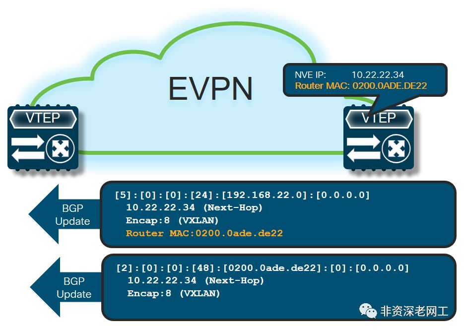
接下来我们利用 GoBGP 向 NXOS 发送 RT-2 路由更新。RT-2 路由的作用是向 Fabric 通告 MAC/IP 的位置。根据 RFC-7432,RT-2 的 NLRI 格式如下:
            +---------------------------------------+
            |  RD (8 octets)                        |
            +---------------------------------------+
            |Ethernet Segment Identifier (10 octets)|
            +---------------------------------------+
            |  Ethernet Tag ID (4 octets)           |
            +---------------------------------------+
            |  MAC Address Length (1 octet)         |
            +---------------------------------------+
            |  MAC Address (6 octets)               |
            +---------------------------------------+
            |  IP Address Length (1 octet)          |
            +---------------------------------------+
            |  IP Address (0, 4, or 16 octets)      |
            +---------------------------------------+
            |  MPLS Label1 (3 octets)               |
            +---------------------------------------+
            |  MPLS Label2 (0 or 3 octets)          |
            +---------------------------------------+
在 VXLAN 场景,MPLS Label 就是 VNI,第 1 个是 L2VNI,第 2 个是 L3VNI。GoBGP 发送 RT-2 的命令格式为:
$ gobgp global rib -a evpn add macadv <mac address> <ip address> [origin { igp | egp | incomplete }] [esi <esi>] etag <etag> label <label> rd <rd> [rt <rt>...] [encap <encap type>] [router-mac <mac address>] [default-gateway]
其中 ESI 和 Etag 的 Value 应该是什么呢?我们先来看看 NXOS 向邻居通告的路由信息是怎样的:
R2-VTEP# show bgp l2vpn evpn neighbors 10.0.0.1 advertised-routes

...(snip)

   Network            Next Hop            Metric     LocPrf     Weight Path
Route Distinguisher: 50200:1    (L2VNI 50200)
*>l[2]:[0]:[0]:[48]:[000c.298c.0cfa]:[0]:[0.0.0.0]/216
                      10.0.0.2                          100      32768 i
*>l[2]:[0]:[0]:[48]:[000c.298c.0cfa]:[32]:[172.16.2.10]/272
                      10.0.0.2                          100      32768 i

Route Distinguisher: 50300:1    (L2VNI 50300)
*>l[2]:[0]:[0]:[48]:[000c.2996.007a]:[0]:[0.0.0.0]/216
                      10.0.0.2                          100      32768 i
*>l[2]:[0]:[0]:[48]:[000c.2996.007a]:[32]:[172.16.3.20]/272
                      10.0.0.2                          100      32768 i

Route Distinguisher: 50999:1    (L3VNI 50999)
R2-VTEP 连接了 2 个 Host,H1 和 H2,分别位于 2 个不同的 Subnet,对应 2 个不同的 L2VNI。它为每个 Host 向每个 L2 RD 通告了 2 条路由:一条通告 MAC,用于 Bridging;另外一条通告 MAC/IP,用于 Routing。然后我们再观察每个 MAC 对应的路由详细内容:
R2-VTEP# show bgp l2vpn evpn 000c.298c.0cfa
BGP routing table information for VRF default, address family L2VPN EVPN
Route Distinguisher: 50200:1    (L2VNI 50200)
BGP routing table entry for [2]:[0]:[0]:[48]:[000c.298c.0cfa]:[0]:[0.0.0.0]/216,
 version 301
Paths: (1 available, best #1)
Flags: (0x000102) (high32 00000000) on xmit-list, is not in l2rib/evpn
Multipath: iBGP

  Advertised path-id 1
  Path type: local, path is valid, is best path
  AS-Path: NONE, path locally originated
    10.0.0.2 (metric 0) from 0.0.0.0 (10.0.0.2)
      Origin IGP, MED not set, localpref 100, weight 32768
      Received label 50200
      Extcommunity: RT:50200:1 ENCAP:8

  Path-id 1 advertised to peers:
    10.0.0.1
BGP routing table entry for [2]:[0]:[0]:[48]:[000c.298c.0cfa]:[32]:[172.16.2.10]
/272, version 90
Paths: (1 available, best #1)
Flags: (0x000102) (high32 00000000) on xmit-list, is not in l2rib/evpn
Multipath: iBGP

  Advertised path-id 1
  Path type: local, path is valid, is best path
  AS-Path: NONE, path locally originated
    10.0.0.2 (metric 0) from 0.0.0.0 (10.0.0.2)
      Origin IGP, MED not set, localpref 100, weight 32768
      Received label 50200 50999
      Extcommunity: RT:50200:1 RT:50999:1 ENCAP:8 Router MAC:000c.2964.0298

  Path-id 1 advertised to peers:
    10.0.0.1
用于 Bridging 的路由仅携带了 L2VNI 和 MAC VRF 的 RT,而用于 Routing 的路由则同时携带了 L2VNI、 L3VNI 以及 MAC VRF 和 IP VRF 的 RT,还有 NVE Tunnel 接口的 MAC。在路由信息中, [2]:[0]:[0]:[48]
的含义是:
[2] :Route Type 2
第 1 个 [0] :Ethernet Segment Identifier
第 2 个 [0] :Ethernet Tag ID
[48] :MAC 地址长度
从上面的 show
结果,我们可以知道正常的 RT-2 路由都应该包括哪些内容。我们先使用 GoBGP 向 Fabric 通告一个并不存在 Host(GoBGP 不支持将直连网段重分布到 BGP。需要安装 Quagga/FRR 然后通过 Zebra API 才能将直连路由或其他协议的路由重分布到 BGP),MAC 地址为 aa:bb:cc:dd:ee:ff,IP 地址为 172.16.2.20,和 H2 属于同一个子网:
# 通告 MAC
$ ./gobgp global rib -a evpn add macadv aa:bb:cc:dd:ee:ff 0.0.0.0 esi 0 etag 0 label 50200 rd 50200:1 rt 50200:1 encap vxlan
# 通告 MAC/IP
$ ./gobgp global rib -a evpn add macadv aa:bb:cc:dd:ee:ff 172.16.2.20 esi 0 etag 0 label 50200,50999 rd 50200:1 rt 50200:1 50999:1 encap vxlan router-mac 000c.298d.eb0a
在 R2-VTEP 上可以观察到已经收到这 2 条 RT-2 路由并加表:
R2-VTEP# show bgp l2vpn evpn

...(snip)

Route Distinguisher: 50200:1    (L2VNI 50200)
*>l[2]:[0]:[0]:[48]:[000c.298c.0cfa]:[0]:[0.0.0.0]/216
                      10.0.0.2                          100      32768 i
*>i[2]:[0]:[0]:[48]:[aabb.ccdd.eeff]:[0]:[0.0.0.0]/216
                      10.15.0.100                       100          0 ?
*>l[2]:[0]:[0]:[48]:[000c.298c.0cfa]:[32]:[172.16.2.10]/272
                      10.0.0.2                          100      32768 i
*>i[2]:[0]:[0]:[48]:[aabb.ccdd.eeff]:[32]:[172.16.2.20]/272
                      10.15.0.100                       100          0 ?
...(snip)

R2-VTEP# show ip route vrf Tenant1
...(snip)

172.16.2.20/32, ubest/mbest: 1/0
    *via 10.15.0.100%default, [200/0], 00:11:28, bgp-65000, internal, tag 65000
(evpn) segid: 50999 tunnelid: 0xa0f0064 encap: VXLAN

...(snip)
并且 R2-VTEP 已经和 H5-GoBGP 成功建立了 NVE Peer:
R2-VTEP# show nve peers
Interface Peer-IP          State LearnType Uptime   Router-Mac
--------- ---------------  ----- --------- -------- -----------------
nve1      10.0.0.3         Up    CP        03:15:43 000c.29c7.522d
nve1      10.15.0.100      Up    CP        00:17:50 000c.298d.eb0a
6.1 ARP 报文传输路径
在 H2 上 ping 相同子网的 172.16.2.20,然后在 ESXi 上抓取 H2 的流量,发现 H2 发送 ARP 请求 172.16.2.20 的 MAC,但一直没有收到 ARP Response。在 H5 上抓包,发现并没有抓取到 ICMP 或 ARP 报文。
但是在 H3 上 ping 不同子网的 172.16.2.20,却可以在 H5 上抓取到 ICMP 报文。从下面的截图可以看到 ICMP 报文有 VXLAN 的报头,目的 VTEP IP 是 10.15.0.100,因为是 Inter-Subnet 的流量,所以封装的 VNI 是 L3VNI 50999。然后 H5 向 R3 回应了 ICMP 不可达:

这是因为在 H3 在请求 172.16.2.20 的 MAC 的时候,Anycast Gateway R3 会将自己的 MAC 回应给 H3,也就是 fabric forwarding anycast-gateway-mac0001.0001.0001
所配置的 MAC 地址:

而 H2 所请求的是相同子网的 MAC,虽然在 R2-VTEP 上存在去往 172.16.2.20 的 EVPN 路由,但为了处理 BUM 流量,例如 ARP,R2-VTEP 需要将 ARP Request 用 VXLAN 封装之后发往组播地址,本实验我们所配置的组播地址是 239.0.0.1。其他 VTEP 收到 ARP Request 之后会解封装并检查所请求的地址是否在本地,如果不在本地则丢弃,如果在本地就发给目的主机,然后由目的主机单播回复 ARP Response。
H5-GoBGP 并没有办法像 NXOS 那样为 L2VNI 指定一个组播地址加入组播组,所以它无法收到 ARP。我们采用一个变通的办法,在 R1-Spine 上将连接 H5-GoBGP 的接口加入到组播组:
interface Ethernet1/4
  description to H5-GoBGP
  ip igmp join-group 239.0.0.1
然后在 H2 上 ping 172.16.2.20,就可以在 H5 上抓到 ARP Request 报文了:
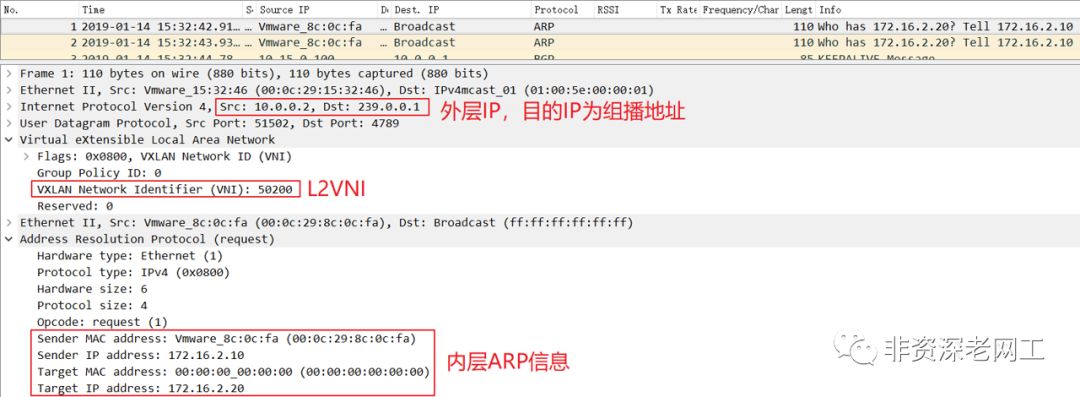
在上面的截图我们可以看到 VXLAN Outer 目的 IP 是 239.0.0.1。因为是 Intra-Subnet 的流量,所以封装的 VNI 是 L2VNI 50200。
当然也可以改用 BGP 而不使用组播的方式来复制 BUM,需要更改 intnve1
的配置:
interface nve1
  no shutdown
  host-reachability protocol bgp
  source-interface loopback0
  member vni 50200
    ingress-replication protocol bgp
在没有组播的情况下,就需要另外一种路由:Route Type 3 —— Inclusive Multicast Ethernet Tag route。每台 VTEP 需要先向所有相关的 MAC VRF RD 通告 RT-3,告诉其他 VTEP 应该把 BUM 复制到哪里,然后再按照上文介绍的流程通告 RT-2。
RT-3 NLRI 的格式如下:
           +---------------------------------------+
           |  RD (8 octets)                        |
           +---------------------------------------+
           |  Ethernet Tag ID (4 octets)           |
           +---------------------------------------+
           |  IP Address Length (1 octet)          |
           +---------------------------------------+
           |  Originating Router's IP Address      |
           |          (4 or 16 octets)             |
           +---------------------------------------+
同时,BGP Extended Communities 必须要携带 RFC 6514 所定义的 Provider Multicast Service Interface (PMSI) Tunnel 属性,以实现这种 Point-to-Multipoint 的复制。PMSI BGP 属性的格式如下:
           +---------------------------------+
           |  Flags (1 octet)                |
           +---------------------------------+
           |  Tunnel Type (1 octets)         |
           +---------------------------------+
           |  MPLS Label (3 octets)          |
           +---------------------------------+
           |  Tunnel Identifier (variable)   |
           +---------------------------------+
其中 Flags 只定义了一种:Leaf Information Required (L)。在 VXLAN EVPN 的场景,Tunnel Type 的值是 6,表示这是 Ingress Replication。剩下 2 个字段就比较好理解了,分别是 VNI 和本地 NVE 接口的 IP 地址。
GoBGP 通告 RT-3 的 CLI 格式为:
$ gobgp global rib -a evpn add multicast <ip address> etag <etag> rd <rd> [rt <rt>...] [encap <encap type>] [pmsi <type> [leaf-info-required] <label> <tunnel-id>]
其中 <ipaddress>
就是 Originating Router's IP Address,而 <tunnel-id>
的值和 <ipaddress>
是一样的。我们可以在 GoBGP 上使用命令 gobgpglobalrib-a evpn
来看看 Cisco NXOSv 发给 GoBGP 的 RT-3 更新,比较一下 <ipaddress>
和 <tunnel-id>
:

在上面的截图中,我们也可以看到 pmsi type 是 ingress-repl
。
需要注意的是,GoBGP v1.3.3 在通告 RT-3 的时候会提示 runtime error,建议大家使用 v2.0.0 版本。
现在我们再回过头来看看 Ethernet Segment Identifier 和 Ethernet Tag ID。
6.2 Ethernet Segment Identifier
我们知道数据中心为了给服务器提供链路冗余,通常会采用 2 台 Leaf 堆叠的方式。但堆叠之后交换机升级会影响业务连续性,而且有可能会出现一些奇葩的问题。RFC-7432 提供了一种去堆叠的方式:EVPN multi-homing。
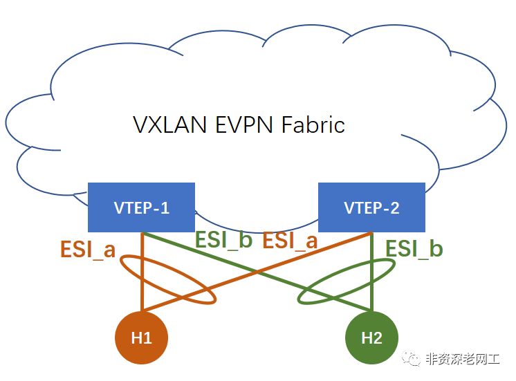
在 EVPN multi-homing 的场景,服务器正常 bonding 2 条 uplink,但 VTEP-1 和 VTEP-2 之间并没有 peer-link,需要通过 EVPN Fabric 来交换信息。它们交换的就是 ESI 和 Etag。ESI 配置在每条 bundled link 上,如果相同 Domain 的 VTEP 有相同的 ESI,它们就会共享 multihomed neighbor。这种场景需要用到 Route Type 1 Auto-Discovery 路由。
本实验的服务器都采用单挂,single-homing,所以 ESI 为 0。
除了采用 ESI 来实现 multi-homing 之外,以阿里为代表的国内互联网公司正在使用另外一种去堆叠方式,Cisco 对应的技术是 VPC-less,即 VPC without peering link。
6.3 Ethernet Tag ID
Etag 的作用是在 EVPN Instance 中标识一个特定的广播域(Bridge Table)。一个 EVPN Instance 就是一个 MAC-VRF,包含 1 个或多个 Bridge Table,这些 BT 共享相同的 Route Target。
在 Asymmetric IRB 模型中,1 个 MAC-VRF/EVI 会包含多个 BT。但是在 Symmetric IRB 操作模型中,1 个 MAC-VRF 仅包含 1 个 BT,是 1:1 的 mapping 关系,请看下面的 NXOS 相关配置:
vlan 200
  name L2-VNI-50200-Tenant1
  vn-segment 50200

evpn
  vni 50200 l2
    rd 50200:1
    route-target import 50200:1
    route-target export 50200:1
所以在 Symmetric IRB 模型中,Etag 必须置为 0,不需要用它来区分广播域。
7. Route-Type 5: IP Prefix Route
接下来我们让 H5 作为 EVPN Border,测试 RT-5 路由。由于 GoBGP 必须与 Quagga/FRR 的 Zebra API 集成,才能重分发外部路由到 BGP,所以这次实验我们仍然只能用 1 个虚拟的 IP 地址作为目的 IP。
GoBGP 通告 RT-5 的 CLI 格式是:
$ ./gobgp global rib -a evpn add <ip prefix> [gw <gateway>] [origin { igp | egp | incomplete }] [esi <esi>] etag <etag> [label <label>] rd <rd> [rt <rt>...] [encap <encap type>] [router-mac <mac address>]
从上文的分析中,我们已经知道 esi 和 etag 都为 0。但是 gateway 又是怎么回事?先不管这个,我们直接在 H5 向 Fabric 通告一条 RT-5:
$ ./gobgp global rib -a evpn add prefix \
> 0.0.0.0/0 etag 0 label 50999 rd 50999:1 rt 50999:1 \
> encap vxlan router-mac 000c.298d.eb0a
在 Cisco VTEP 可以观察到已经收到了这条 RT-5 路由:
R3-VTEP# sh bgp l2vpn evpn
...(snip)

Route Distinguisher: 50999:1
*>i[5]:[0]:[0]:[0]:[0.0.0.0]:[0.0.0.0]/224
                      10.15.0.100                       100          0 ?

Route Distinguisher: 50999:1    (L3VNI 50999)
*>i[2]:[0]:[0]:[48]:[000c.298c.0cfa]:[32]:[172.16.2.10]/272
                      10.0.0.2                          100          0 i
*>i[2]:[0]:[0]:[48]:[000c.2996.007a]:[32]:[172.16.3.20]/272
                      10.0.0.2                          100          0 i
*>i[5]:[0]:[0]:[0]:[0.0.0.0]:[0.0.0.0]/224
                      10.15.0.100                       100          0 ?

R3-VTEP# sh ip route vrf Tenant1
...(snip)

0.0.0.0/0, ubest/mbest: 1/0
    *via 10.15.0.100%default, [200/0], 00:01:01, bgp-65000, internal, tag 65000
(evpn) segid: 50999 tunnelid: 0xa0f0064 encap: VXLAN

...(snip)
在 H3 上 ping 一个路由表里不存在的地址 100.100.100.100,然后可以在 H5 上抓取到这些 ICMP 报文,RT-5 路由生效了:

另外请注意 Inner MAC(我忘记用红色框出来了),这是在 RT-2 和 RT-5 路有更新中所携带的 router-mac
属性。
H5-GoBGP 在通告 RT-5 路由的时候,并没有携带 [gw<gateway>]
参数,那么这个参数的作用是什么呢?
上文已经谈到 Cisco 采用的 Inter-Subnet 操作模型是 Symmetric IRB。在这个 IRB 模型中,Inter-Subnet 路由是 IP-VRF to IP-VRF。在 draft-ietf-bess-evpn-prefix-advertisement 中又定义了 3 种 IP-VRF-to-IP-VRF 模型,分别是:
Interface-less IP-VRF-to-IP-VRF Model
Interface-ful IP-VRF-to-IP-VRF with SBD IRB
Interface-ful IP-VRF-to-IP-VRF with Unnumbered SBD IRB
7.1 Interface-less IP-VRF-to-IP-VRF Model
Cisco Nexus 采用的就是这种最简单的模型,IP-VRF 直连 IP-VRF,不需要额外的 Overlay Index。正如我们刚才所操作的那样,在这种模型中,Border Node 只需要通告 1 条 RT-5 路由并且不需要携带 GW 参数,只需要携带 router-mac
参数把自己的 NVE 接口的 MAC 地址通告出去。其他 VTEP 在收到这条 RT-5 路由之后,会将 next-hop 指向 Border 的 NVE 接口。
7.2 Interface-ful IP-VRF-to-IP-VRF with SBD IRB
这种模型是最复杂的,IP-VRF 不能直连其他 VTEP 的 IP-VRF,需要一个 Supplementary Broadcast Domain (SBD) 作为一个 “Super IRB”,连接租户所有的 IP-VRF。SBD 还需要有自己的 IP 地址和 MAC 地址。同样地,在 Border Node (Datacenter GW) 上也需要有 SBD。
                 NVE1
        +------------+                       DGW1
IP10+---+(BD-1)      | +---------------+ +------------+
        |  \         | |               | |            |
        |(IP-VRF)-(SBD)|               |(SBD)-(IP-VRF)|-----+
        |  /    IRB(IP1/M1)           IRB(IP3/M3)     |     |
    +---+(BD-2)      | |               | +------------+    _+_
    |   +------------+ |               |                  (   )
 SN1|                  |     VXLAN/    |                 ( WAN )--H1
    |            NVE2  |     GENEVE/   |                  (___)
    |   +------------+ |     MPLS      |     DGW2           +
    +---+(BD-2)      | |               | +------------+     |
        |  \         | |               | |            |     |
        |(IP-VRF)-(SBD)|               |(SBD)-(IP-VRF)|-----+
        |  /    IRB(IP2/M2)           IRB(IP4/M4)     |
SN2+----+(BD-3)      | +---------------+ +------------+
        +------------+
         图12. Interface-ful with SBD IRB model
在这个操作模型中,Border 需要通告 2 条路由:
1 条 RT-5,通告 Prefix,同时把自己的 SBD IRB 的 IP 地址作为 GW 通告出去。GoBGP 的
[gw<gateway>]
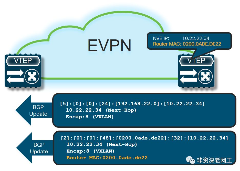
参数就是为这个模型准备的1 条 RT-2,向 Fabric 通告自己的 SBD IRB 的 MAC/IP,同时还要携带
router-mac
Ext-community
7.3 Interface-ful IP-VRF-to-IP-VRF with Unnumbered SBD IRB
这种模型相对简单一点,VTEP 和 Border 同样需要 SBD 作为 overlay index,但 SBD IRB 不再需要 IP 地址,只需要 MAC 地址。
                 NVE1
        +------------+                       DGW1
IP1+----+(BD-1)      | +---------------+ +------------+
        |  \         | |               | |            |
        |(IP-VRF)-(SBD)|               (SBD)-(IP-VRF) |-----+
        |  /    IRB(M1)|               | IRB(M3)      |     |
    +---+(BD-2)      | |               | +------------+    _+_
    |   +------------+ |               |                  (   )
 SN1|                  |     VXLAN/    |                 ( WAN )--H1
    |            NVE2  |     GENEVE/   |                  (___)
    |   +------------+ |     MPLS      |     DGW2           +
    +---+(BD-2)      | |               | +------------+     |
        |  \         | |               | |            |     |
        |(IP-VRF)-(SBD)|               (SBD)-(IP-VRF) |-----+
        |  /    IRB(M2)|               | IRB(M4)      |
SN2+----+(BD-3)      | +---------------+ +------------+
        +------------+
        图14. Interface-ful with unnumbered SBD IRB model
在这个操作模型中,Border 也还是需要通告 2 条路由:
1 条 RT-5,通告 Prefix,不需要携带 GW,但需要携带
router-mac
Ext-community1 条 RT-2,仅向 Fabric 通告自己的 SBD IRB 的 MAC
8. GoBGP 分布式部署
上面的实验拓扑是单节点 GoBGP,但我们可以利用 nexthop
参数,在发送路由更新的时候携带 NextHop Attribute 来实现 GoBGP 的分布式部署。在 Github 的 Docs 里面并没有介绍 nexthop 参数,CLI 命令帮助也没有标识它,是一个“隐藏”参数:

在发布 NextHop Attribute 之后,所有安装了 GoBGP 的 Linux Server 都可以采用相同的 VTEP 虚拟 IP/MAC 地址,实现类似vPCVIP 或Multi-siteBorder VIP 的效果:

本文首发 SDNLAB,拖了一年才放到自己的公号上...有补充一些内容,点击“阅读原文”可以访问 SDNLAB 的原文。
参考:
[1] https://github.com/osrg/gobgp/blob/master/docs/sources/evpn.md [2] https://github.com/osrg/gobgp/blob/master/docs/sources/cli-command-syntax.md [3] http://www.slideshare.net/shusugimoto1986/tutorial-using-gobgp-as-an-ixp-connecting-router [4] https://ciscolive.cisco.com/on-demand-library/?search=3378#/session/1509501642097001PzUe [5] https://tools.ietf.org/html/rfc6514 [6] https://tools.ietf.org/html/rfc7432


