


2015CVPR最佳论文-动态融合:实时非刚性场景的重建与跟踪.pdf
50墨值下载

DynamicFusion: Reconstruction and Tracking of Non-rigid Scenes in Real-Time
Richard A. Newcombe
newcombe@cs.washington.edu
Dieter Fox
fox@cs.washington.edu
University of Washington, Seattle
Steven M. Seitz
seitz@cs.washington.edu
Figure 1: Real-time reconstructions of a moving scene with DynamicFusion; both the person and the camera are moving. The initially
noisy and incomplete model is progressively denoised and completed over time (left to right).
Abstract
We present the first dense SLAM system capable of re-
constructing non-rigidly deforming scenes in real-time, by
fusing together RGBD scans captured from commodity sen-
sors. Our DynamicFusion approach reconstructs scene ge-
ometry whilst simultaneously estimating a dense volumet-
ric 6D motion field that warps the estimated geometry into
a live frame. Like KinectFusion, our system produces in-
creasingly denoised, detailed, and complete reconstructions
as more measurements are fused, and displays the updated
model in real time. Because we do not require a template
or other prior scene model, the approach is applicable to a
wide range of moving objects and scenes.
3D scanning traditionally involves separate capture and
off-line processing phases, requiring very careful planning
of the capture to make sure that every surface is cov-
ered. In practice, it’s very difficult to avoid holes, requir-
ing several iterations of capture, reconstruction, identifying
holes, and recapturing missing regions to ensure a complete
model. Real-time 3D reconstruction systems like KinectFu-
sion [18, 10] represent a major advance, by providing users
the ability to instantly see the reconstruction and identify
regions that remain to be scanned. KinectFusion spurred a
flurry of follow up research aimed at robustifying the track-
ing [9, 32] and expanding its spatial mapping capabilities to
larger environments [22, 19, 34, 31, 9].
However, as with all traditional SLAM and dense re-
construction systems, the most basic assumption behind
KinectFusion is that the observed scene is largely static.
The core question we tackle in this paper is: How can we
generalise KinectFusion to reconstruct and track dynamic,
non-rigid scenes in real-time? To that end, we introduce
DynamicFusion, an approach based on solving for a vol-
umetric flow field that transforms the state of the scene at
each time instant into a fixed, canonical frame. In the case
of a moving person, for example, this transformation un-
does the person’s motion, warping each body configuration
into the pose of the first frame. Following these warps, the
scene is effectively rigid, and standard KinectFusion up-
dates can be used to obtain a high quality, denoised recon-
struction. This progressively denoised reconstruction can
then be transformed back into the live frame using the in-
verse map; each point in the canonical frame is transformed
to its location in the live frame (see Figure 1).
Defining a canonical “rigid” space for a dynamically
moving scene is not straightforward. A key contribution
of our work is an approach for non-rigid transformation and
fusion that retains the optimality properties of volumetric
scan fusion [5], developed originally for rigid scenes. The
main insight is that undoing the scene motion to enable fu-
sion of all observations into a single fixed frame can be
achieved efficiently by computing the inverse map alone.
Under this transformation, each canonical point projects
along a line of sight in the live camera frame. Since the
optimality arguments of [5] (developed for rigid scenes) de-
pend only on lines of sight, we can generalize their optimal-
ity results to the non-rigid case.
Our second key contribution is to represent this volumet-
ric warp efficiently, and compute it in real time. Indeed,
even a relatively low resolution, 256
3
deformation volume
would require 100 million transformation variables to be
computed at frame-rate. Our solution depends on a com-
bination of adaptive, sparse, hierarchical volumetric basis
functions, and innovative algorithmic work to ensure a real-
time solution on commodity hardware. As a result, Dynam-
icFusion is the first system capable of real-time dense recon-
struction in dynamic scenes using a single depth camera.
The remainder of this paper is structured as follows. Af-
ter discussing related work, we present an overview of Dy-
namicFusion in Section 2 and provide technical details in
Section 3. We provide experimental results in Section 4 and
conclude in Section 5.
1. Related Work
While no prior work achieves real-time, template-free,
non-rigid reconstruction, there are two categories of closely
related work: 1) real-time non-rigid tracking algorithms,
and 2) offline dynamic reconstruction techniques.
Real-time non-rigid template tracking. The vast ma-
jority of non-rigid tracking research focuses on human body
parts, for which specialised shape and motion templates are
learnt or manually designed. The best of these demonstrate
high accuracy, real-time performance capture for tracking
faces [16, 3], hands [21, 20], complete bodies [27], or gen-
eral articulated objects [23, 33].
Other techniques directly track and deform more gen-
eral mesh models. [12] demonstrated the ability to track
a statically acquired low resolution shape template and up-
grade its appearance with high frequency geometric details
not present in the original model. Recently, [37] demon-
strated an impressive real-time version of a similar tech-
nique, using GPU accelerated optimisations. In that sys-
tem, a dense surface model of the subject is captured while
remaining static, yielding a template for use in their real-
time tracking pipeline. This separation into template gen-
eration and tracking limits the system to objects and scenes
that are completely static during the geometric reconstruc-
tion phase, precluding reconstruction of things that won’t
reliably hold still (e.g., children or pets).
Offline simultaneous tracking and reconstruction of
dynamic scenes. There is a growing literature on offline
non-rigid tracking and reconstruction techniques. Several
researchers have extended ICP to enable small non-rigid
deformations, e.g., [1, 2]. Practical advancements to pair-
wise 3D shape and scan alignment over larger deformations
make use of reduced deformable model parametrisations
[14, 4]. In particular, embedded deformation graphs [25]
use a sparsely sampled set of transformation basis func-
tions that can be efficiently and densely interpolated over
space. Quasi-rigid reconstruction has also been demon-
strated [15, 35] and hybrid systems, making use of a known
kinematic structure (e.g., a human body), are able to per-
form non-rigid shape denoising [36]. Other work combines
non-rigid mesh template tracking and temporal denoising
and completion [13], but does not obtain a single consistent
representation of the scene.
More closely related to our work are template-free tech-
niques. An intriguing approach to template-free non-rigid
alignment, introduced in [17] and [26], treats each non-
rigid scan as a view from a 4D geometric observation and
performs 4D shape reconstruction. [30, 29] reconstruct
a fixed topology geometry by performing pair-wise scan
alignment. [24] use a space-time solid incompressible flow
prior that results in water tight reconstructions and is ef-
fective against noisy input point-cloud data. [28] intro-
duce animation cartography that also estimates shape and
a per frame deformation by developing a dense correspon-
dence matching scheme that is seeded with sparse landmark
matches. Recent work using multiple fixed kinect cameras
[8] [7] demonstrates larger scale non-rigid reconstruction by
densely tracking and fusing all depth map data into a novel
directional distance function representation.
All of these techniques require three to four orders of
magnitude more time than is available within a real-time
setting.
2. DynamicFusion Overview
DynamicFusion decomposes a non-rigidly deforming
scene into a latent geometric surface, reconstructed into a
rigid canonical space S ⊆ R
3
; and a per frame volumetric
warp field that transforms that surface into the live frame.
There are three core algorithmic components to the system
that are performed in sequence on arrival of each new depth
frame:
1. Estimation of the volumetric model-to-frame warp
field parameters (Section 3.3)
2. Fusion of the live frame depth map into the canonical
space via the estimated warp field (Section 3.2)
3. Adaptation of the warp-field structure to capture newly
added geometry (Section 3.4)
Figure 2 provides an overview.
3. Technical Details
We will now describe the components of DynamicFusion
in detail. First, we describe our dense volumetric warp-field
parametrisation. This allows us to model per-frame defor-
mations in the scene. The warp-field is the key extension
over static state space representations used in traditional re-
construction and SLAM systems, and its estimation is the
enabler of both non-rigid tracking and scene reconstruction.
3.1. Dense Non-rigid Warp Field
We represent dynamic scene motion through a volumet-
ric warp-field, providing a per point 6D transformation
W : S 7→ SE(3). Whereas a dense 3D translation field
would be sufficient to describe time varying geometry, we
have found that representing the real-world transformation
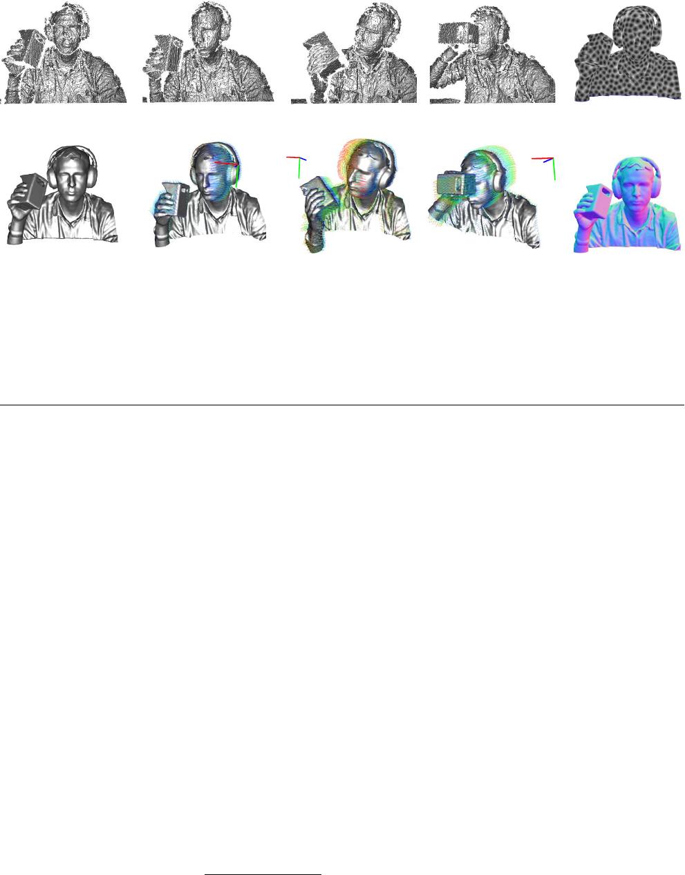
(a) Initial Frame at t = 0s (b) Raw (noisy) depth maps for frames at t = 1s, 10s, 15s, 20s (c) Node Distance
(d) Canonical Model (e) Canonical model warped into its live frame (f) Model Normals
Figure 2: DynamicFusion takes an online stream of noisy depth maps (a,b) and outputs a real-time dense reconstruction of the moving
scene (d,e). To achieve this, we estimate a volumetric warp (motion) field that transforms the canonical model space into the live frame,
enabling the scene motion to be undone, and all depth maps to be densely fused into a single rigid TSDF reconstruction (d,f). Simulta-
neously, the structure of the warp field is constructed as a set of sparse 6D transformation nodes that are smoothly interpolated through
a k-nearest node average in the canonical frame (c). The resulting per-frame warp field estimate enables the progressively denoised and
completed scene geometry to be transformed into the live frame in real-time (e). In (e) we also visualise motion trails for a sub-sample
of model vertices over the last 1 second of scene motion together with a coordinate frame showing the rigid body component of the scene
motion. In (c) we render the nearest node to model surface distance where increased distance is mapped to a lighter value.
of objects with both translation and rotation results in signif-
icantly better tracking and reconstruction. For each canoni-
cal point v
c
∈ S, T
lc
= W(v
c
) transforms that point from
canonical space into the live, non-rigidly deformed frame of
reference.
Since we will need to estimate the warp function for each
new frame, W
t
, its representation must be efficiently opti-
misable. One possibility is to densely sample the volume,
e.g. representing a quantised SE(3) field at the resolution
of the truncated signed distance (TSDF) geometric repre-
sentation. However, a typical TSDF volume reconstruction
at a relatively low resolution of 256
3
voxels would require
the solution of 6 × 256
3
parameters per frame, about 10
million times more than in the original KinectFusion al-
gorithm, which only estimates a single rigid transforma-
tion. Clearly, a completely dense parametrisation of the
warp function is infeasible. In reality, surfaces tend to move
smoothly in space, and so we can instead use a sparse set
of transformations as bases and define the dense volumet-
ric warp function through interpolation. Due to its compu-
tational efficiency and high quality interpolation capability
we use dual-quaternion blending DQB [11], to define our
warp function:
W(x
c
) ≡ SE3(DQB(x
c
)) , (1)
where the weighted average over unit dual quaternion trans-
formations is simply DQB(x
c
) ≡
P
k∈N (x
c
)
w
k
(x
c
)ˆq
kc
k
P
k∈N (x
c
)
w
k
(x
c
)ˆq
kc
k
,
with each unit dual-quaternion ˆq
kc
∈ R
8
. Here, N (x) are
the k-nearest transformation nodes to the point x and w
k
:
R
3
7→ R defines a weight that alters the radius of influence
of each node and SE3(.) converts from quaternions back to
an SE(3) transformation matrix. The state of the warp-field
W
t
at time t is defined by the values of a set of n defor-
mation nodes N
t
warp
= {dg
v
, dg
w
, dg
se3
}
t
. Each of the
i = 1..n nodes has a position in the canonical frame dg
i
v
∈
R
3
, its associated transformation T
ic
= dg
i
se3
, and a ra-
dial basis weight dg
w
that controls the extent of the trans-
formation w
i
(x
c
) = exp
−kdg
i
v
− x
c
k
2
/
2(dg
i
w
)
2
.
Each radius parameter dg
i
w
is set to ensure the node’s in-
fluence overlaps with neighbouring nodes, dependent on
the sampling sparsity of nodes, which we describe in de-
tail in section (3.4). Since the warp function defines a
rigid body transformation for all supported space, both posi-
tion and any associated orientation of space is transformed,
e.g., the vertex v
c
from a surface with orientation or nor-
mal n
c
is transformed into the live frame as (v
t
, 1)
>
=
W
t
(v
c
)(v
>
c
, 1)
>
and (n
t
, 0)
>
= W
t
(v
c
)(n
>
c
, 0)
>
. We note
that scaling of space can also be represented with this warp
function, since compression and expansion of space are rep-
resented by neighbouring points moving in converging and
diverging directions. Finally, we note that we can factor
out any rigid body transformation common to all points in
the volume, e.g., due to camera motion. We therefore in-
troduce the explicit warped model to live camera transform,
T
lw
, and compose this onto the volumetric warp function;
of 11
50墨值下载
【版权声明】本文为墨天轮用户原创内容,转载时必须标注文档的来源(墨天轮),文档链接,文档作者等基本信息,否则作者和墨天轮有权追究责任。如果您发现墨天轮中有涉嫌抄袭或者侵权的内容,欢迎发送邮件至:contact@modb.pro进行举报,并提供相关证据,一经查实,墨天轮将立刻删除相关内容。

下载排行榜
1
2
9-数据库人的进阶之路:从PG分区、SQL优化到拥抱AI未来(罗敏).pptx
3
1-PG版本兼容性案例(彭冲).pptx
4
2-TDSQL PG在复杂查询场景中的挑战与实践-opensource.pdf
5
6-PostgreSQL 哈希索引原理浅析(文一).pdf
6
8-基于PG向量和RAG技术的开源知识库问答系统MaxKB.pptx
7
3-AI时代的变革者-面向机器的接口语言(MOQL)_吕海波.pptx
8
4-IvorySQL V4:双解析器架构下的兼容性创新实践.pptx
9
7-拉起PG好伙伴DifySupaOdoo.pdf
10
《云原生安全攻防启示录》李帅臻.pdf

相关文档
评论