


Setup for Oracle Database Appliance X9-2S X9-2L.pdf
免费下载
1 32
3
4
12 13 14 15
1 2 5 6 7 8 9 10 11 17 18 19 20
16
Node
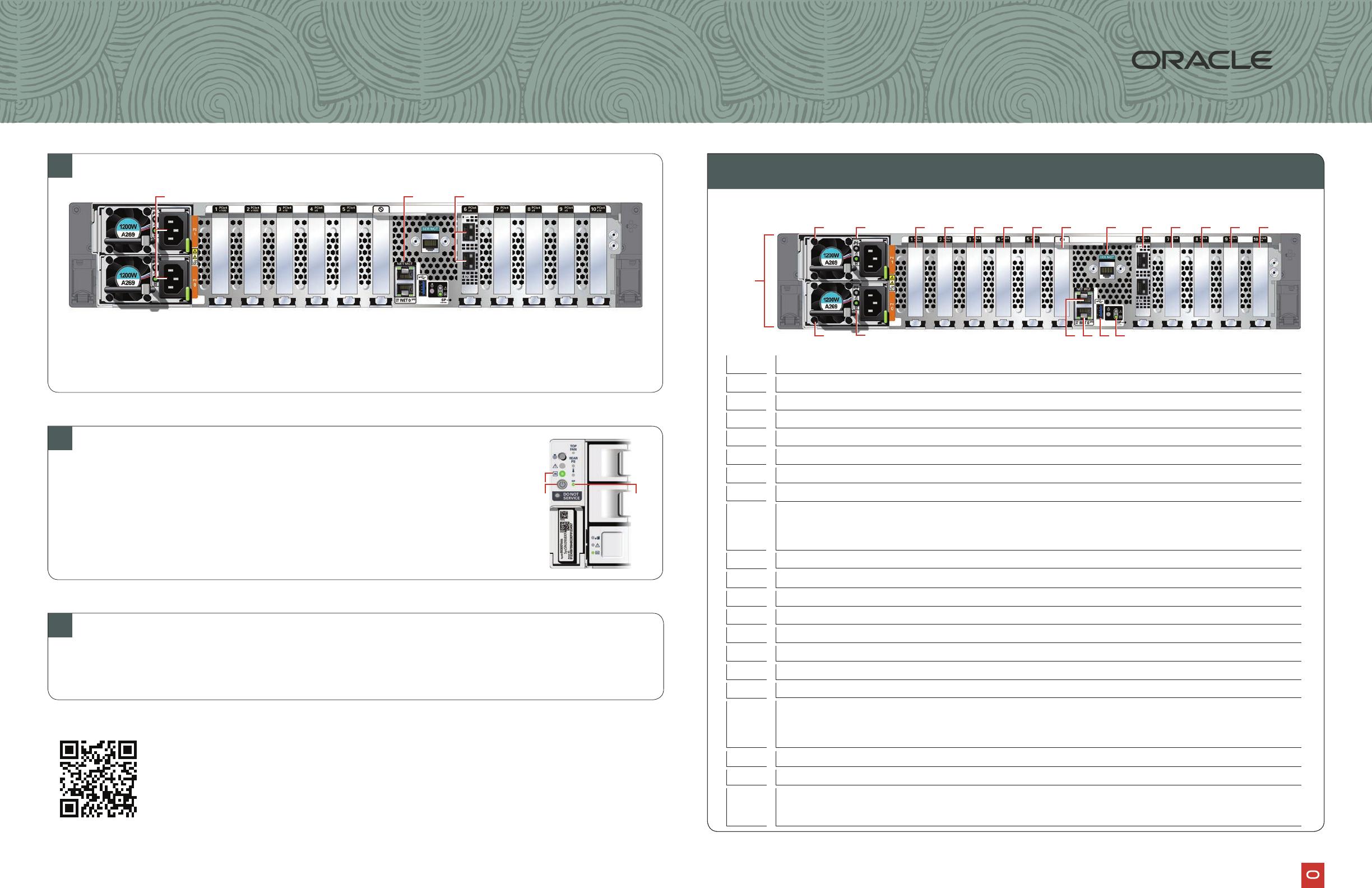
A Plug in AC power to the two power supplies (1) using the power cables included with the system.
For redundancy, each power supply should be connected to a separate AC power source.
B Plug in a network cable to the Oracle Integrated Lights Out Manager (Oracle ILOM)
network management port (2).
C Plug in network cables for public network (3). (Port connections can vary depending on
the option ordered).
1
Server Back Panel Components, Connectors, and Indicators
1
Connect Power and Network Cables
3
Refer to the Oracle Database Appliance Deployment and User’s Guide
To get started with your appliance, refer to the Oracle Database Appliance Welcome Kit at:
2
2
Start Up the System
Power on the host.
indicates that the server is in Standby power mode.
B
C
5
6 4
1
Power Supply (PS) 1 with fan module
2
3
Power Supply (PS) 0 with fan module
4
5
Callout Description
11
12
13
14
USB 3.0 connector
18
PCIe card slot 7:
•
•
19
20
PCIe card slot 10:
•
•
15
16
17
9
7
6
8
For more information about Oracle Database Appliance, go to Oracle Technology Network:
For more information about deployment, go to:
Database Appliance
Setup for Oracle Database Appliance X9-2S / X9-2L
10
Not used
PCIe card slot 4:
•
•
of 1
免费下载
【版权声明】本文为墨天轮用户原创内容,转载时必须标注文档的来源(墨天轮),文档链接,文档作者等基本信息,否则作者和墨天轮有权追究责任。如果您发现墨天轮中有涉嫌抄袭或者侵权的内容,欢迎发送邮件至:contact@modb.pro进行举报,并提供相关证据,一经查实,墨天轮将立刻删除相关内容。
下载排行榜

评论