


Cabling the Interconnect and Storage for Oracle Database Appliance X8-2-HA.pdf
免费下载
1
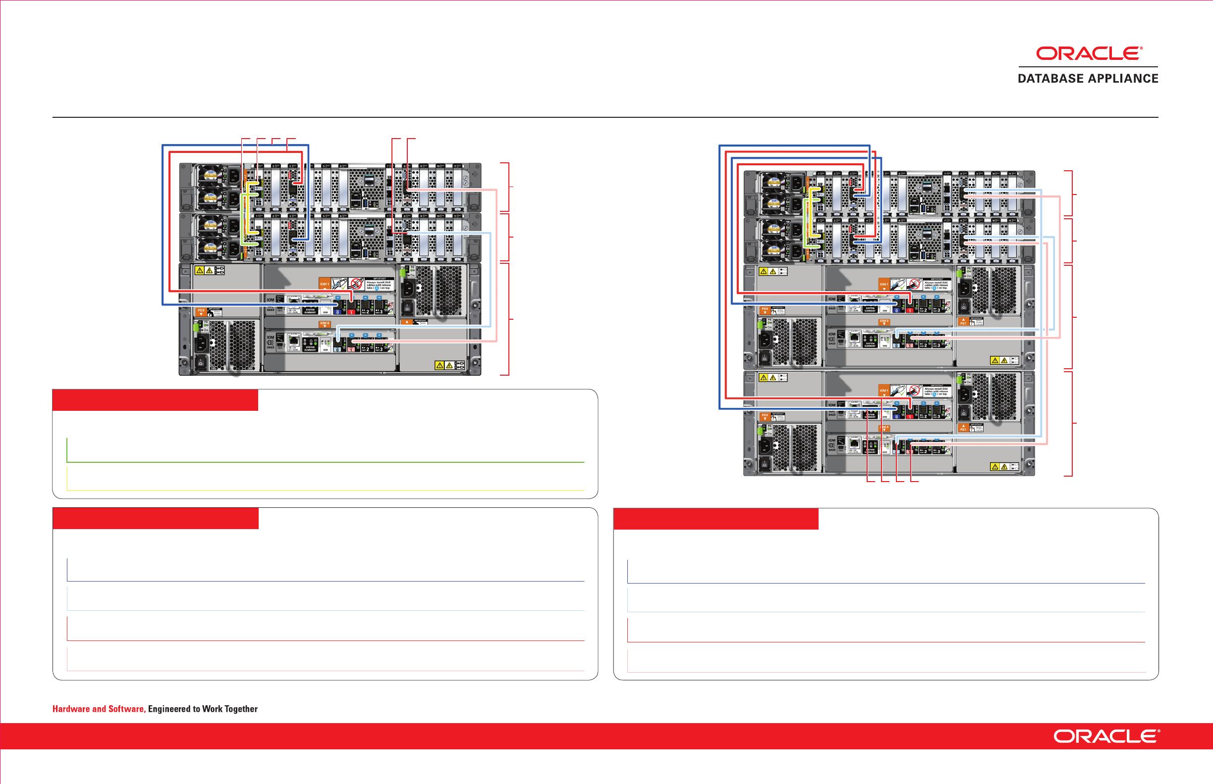
3. Connect dark blue SAS cable Connect into dark blue port
(SAS0) in PCIe slot 3 in Node0
Connect into dark blue port in
top IO Module (PORT 0)
4. Connect light blue SAS cable
Connect into light blue port
(SAS1) in PCIe slot 8 in Node0
Connect into light blue port in
bottom IO Module (PORT 0)
5. Connect dark red SAS cable
Connect into dark red port
(SAS1) in PCIe slot 3 in Node1
Connect into dark red port in
top IO Module (PORT 1)
6. Connect light red SAS cable
Connect into light red port
(SAS0) in PCIe slot 8 in Node1
Connect into light red port in
bottom IO Module (PORT 1)
Purpose
Start - Compute Nodes End - Storage Shelf
Purpose Start - Compute Node0 End - Compute Node1
7. Connect dark blue SAS cable Connect into dark blue port
(SAS0) in PCIe slot 3 in Node1
Connect into dark blue port in
top IO Module (PORT 0)
8. Connect light blue SAS cable
Connect into light blue port
(SAS1) in PCIe slot 8 in Node1
Connect into light blue port in
bottom IO Module (PORT 0)
9. Connect dark red SAS cable
Connect into dark red port
(SAS1) in PCIe slot 3 in Node0
Connect into dark red port in
top IO Module (PORT 1)
10
. Connect light red SAS cable
Connect into light red port
(SAS0) in PCIe slot 8 in Node0
Connect into light red port in
bottom IO Module (PORT 1)
Purpose Start - Compute Nodes
End - Expansion Shelf
Storage Shelf
Storage Expansion Shelf
Network
Cabling the Interconnect and Storage for Oracle Database Appliance X8-2-HA
1
1. Connect green SFP+ cable
Connect into green port (PORT 2) in
PCIe slot 1
Connect into green port (PORT 2) in
PCIe slot 1
2. Connect yellow SFP+ cable
Connect into yellow port (PORT 1) in
PCIe slot 1
Connect into yellow port (PORT 1) in
PCIe slot 1
Node1
Node0
Storage
Shelf
3 51 2 64
Storage
Expansion
Shelf
Node1
Node0
Storage
Shelf
8 1097
Connect optional storage
expansion shelf to Oracle
Database Appliance X8-2-HA.
Note: The following cables are
included as part of the Oracle
Database Appliance shipment.
Copyright © 2019, Oracle and/or its affiliates. All rights reserved. Oracle and Java are registered trademarks of Oracle and/or its affiliates. Other names may be trademarks of their respective owners. F20951-01; Mfg no 8203119
Connect interconnect and
storage to Oracle Database
Appliance X8-2-HA.
Note: The following cables are
included as part of the Oracle
Database Appliance shipment.
3
4
12 13 14 15
1 2 5 6 7 8 9 10 11 17 18 19 2016
Node
Important:
Follow the instructions on Page 1
to cable the server nodes,
storage systems, and
interconnect before proceeding.
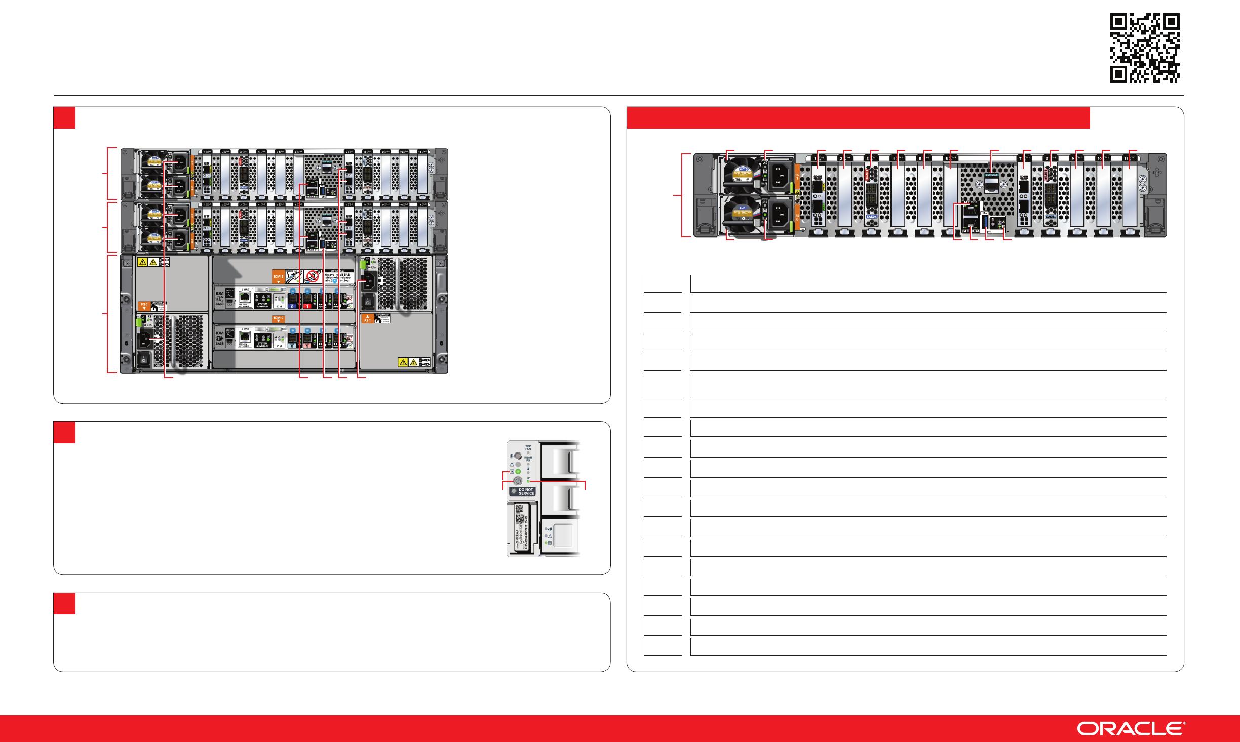
On both nodes, connect:
A Plug in AC power to the
storage shelf and host node
power supplies (1). For
redundancy, ensure that each
component has one of its two
power supply connected to a
separate AC power source.
B Plug in the network cable for
Oracle Integrated Lights Out
Manager (Oracle ILOM)
network management port (2).
C (Optional) On Node0 only,
connect peripheral to USB (3).
D Plug in network cables to the
public network ports (4). (Port
connections can vary depending
on the option ordered).
1
Server Back Panel Components, Connectors, and Indicators
2
Setup for Oracle Database Appliance X8-2-HA
Connect
Power
and
Network Cables
3
Deploy and Configure the Appliance
Refer to the Oracle Database Appliance Deployment and User’s Guide for information about configuring and deploying the appliance.
To get started with your appliance, refer to the Oracle Database Appliance Welcome Kit at:
http://www.oracle.com/goto/oda/docs
Copyright © 2019, Oracle and/or its affiliates. All rights reserved. Oracle and Java are registered trademarks of Oracle and/or its affiliates. Other names may be trademarks of their respective owners. F20951-01; Mfg no 8203119
2
Start Up the Systems
Connect power to the power supply.
A Power on the storage shelf and optional storage expansion shelf using the ON/OFF switch on each power
supply. The storage shelves must be fully powered on (their Power OK LED steady on) before attempting to
power on the host nodes. This can take several minutes depending on the number of drives installed.
B On each node, after the green SP OK LED (5) is steady ON, push the power button (6).
C Wait for the green Power OK LED (7) to turn steady ON. The Power OK LED may blink
for several minutes. Do not repeatedly push the power buttons.
7
6 5
1 4 12 3
Node1
Node0
Storage
Shelf
1
Power Supply (PS) 1 with fan module
2
Power Supply (PS) 1 status indicators: Service Required LED: amber, AC OK LED: green
3
Power Supply (PS) 0 with fan module
4
Power Supply (PS) 0 status indicators: Service Required LED: amber, AC OK LED: green
5
PCIe card slot 1: Oracle Dual Port 25Gb Ethernet Adapter provides two ports with SFP28 connections for a
private cluster interconnect between server nodes
6
PCIe card slot 2: filler panel, or optional Oracle Dual Port 25Gb Ethernet Adapter, or optional Oracle Quad Port 10GBase-T Adapter
Callout Description
11
SER MGT port: RJ-45 serial port used to connect to the Oracle ILOM service processor.
12
NET MGT port: 10/100/1000Base-T network interface port with RJ-45 connector used to connect to the Oracle ILOM service processor.
13
100/1000Base-T network interface port with RJ-45 connector: NET 0
14
USB 3.0 connector
18
PCIe card slot 9: filler panel
19
PCIe card slot 10: filler panel, or optional Oracle Dual Port 25Gb Ethernet Adapter, or optional Oracle Quad Port 10GBase-T Adapter
20
PCIe card slot 11: filler panel
15
System status indicators: Locate LED: white, Service Required LED: amber, Power/OK LED: green
16
PCIe card slot 7: Oracle Dual Port 25Gb Ethernet Adapter or Oracle Quad Port 10GBase-T Adapter
17
PCIe card slot 8: provides two SAS3 connectors used to connect the servers to the storage shelf and the storage expansion shelf
8 -10
PCI card slots 4-6: filler panels
7
PCIe card slot 3: provides two SAS3 connectors used to connect the servers to the storage shelf and the storage expansion shelf
For more information about Oracle Database Appliance, go to Oracle Technology Network: http://www.oracle.com/technetwork/server-storage/engineered-systems/database-appliance/index.html
For more information about deployment, go to: http://www.oracle.com/goto/oda/docs You can also scan the Quick Response Code with your mobile device to read the documentation.
of 2
免费下载
【版权声明】本文为墨天轮用户原创内容,转载时必须标注文档的来源(墨天轮),文档链接,文档作者等基本信息,否则作者和墨天轮有权追究责任。如果您发现墨天轮中有涉嫌抄袭或者侵权的内容,欢迎发送邮件至:contact@modb.pro进行举报,并提供相关证据,一经查实,墨天轮将立刻删除相关内容。

下载排行榜
1
2
9-数据库人的进阶之路:从PG分区、SQL优化到拥抱AI未来(罗敏).pptx
3
1-PG版本兼容性案例(彭冲).pptx
4
2-TDSQL PG在复杂查询场景中的挑战与实践-opensource.pdf
5
6-PostgreSQL 哈希索引原理浅析(文一).pdf
6
3-AI时代的变革者-面向机器的接口语言(MOQL)_吕海波.pptx
7
8-基于PG向量和RAG技术的开源知识库问答系统MaxKB.pptx
8
4-IvorySQL V4:双解析器架构下的兼容性创新实践.pptx
9
7-拉起PG好伙伴DifySupaOdoo.pdf
10
《云原生安全攻防启示录》李帅臻.pdf

相关文档
评论