


【微软2024SIGMOD】Unified Query Optimization in the Fabric Data Warehouse.pdf
免费下载

Unified ery Optimization in the Fabric Data Warehouse
Nicolas Bruno
nicolas.bruno@microsoft.com
Microsoft
Redmond, WA, USA
César Galindo-Legaria
cesarg@microsoft.com
Microsoft
Redmond, WA, USA
Milind Joshi
milind.joshi@microsoft.com
Microsoft
Redmond, WA, USA
Esteban Calvo Vargas
esteban.calvo@microsoft.com
Microsoft
Redmond, WA, USA
Kabita Mahapatra
kabitam@microsoft.com
Microsoft
Redmond, WA, USA
Sharon Ravindran
shravind@microsoft.com
Microsoft
Redmond, WA, USA
Guoheng Chen
guche@microsoft.com
Microsoft
Redmond, WA, USA
Ernesto Cervantes Juárez
ernesto.cervantes@microsoft.com
Microsoft
Redmond, WA, USA
Beysim Sezgin
beysims@microsoft.com
Microsoft
Redmond, WA, USA
ABSTRACT
Over a decade ago, Microsoft introduced Parallel Data Warehouse
(PDW), a massively parallel processing system to manage and
query large amounts of data. Its optimizer was built by reusing
SQL Server’s infrastructure with minimal changes, which was an
eective approach to bring cost-based query optimization quickly
to PDW. Over time, learnings from production as well as architec-
tural changes in the product (such as moving from an appliance
form factor to the cloud, separation of compute and storage, and
serverless components) required evolving the query optimizer in
Fabric DW, the latest oering from Microsoft in the cloud data
warehouse space. In this paper we describe the changes to the
optimization process in Fabric DW, compare them to the earlier
architecture used in PDW, and validate our new approach.
CCS CONCEPTS
• Information systems → Query optimization.
KEYWORDS
Query Optimization; Cascades Framework; Distributed database
systems
ACM Reference Format:
Nicolas Bruno, César Galindo-Legaria, Milind Joshi, Esteban Calvo Vargas,
Kabita Mahapatra, Sharon Ravindran, Guoheng Chen, Ernesto Cervantes
Juárez, and Beysim Sezgin. 2024. Unied Query Optimization in the Fabric
Data Warehouse. In Companion of the 2024 International Conference on
Management of Data (SIGMOD-Companion ’24), June 9–15, 2024, Santiago,
AA, Chile. ACM, New York, NY, USA, 13 pages. https://doi.org/10.1145/
3626246.3653369
Permission to make digital or hard copies of all or part of this work for personal or
classroom use is granted without fee provided that copies are not made or distributed
for prot or commercial advantage and that copies bear this notice and the full citation
on the rst page. Copyrights for components of this work owned by others than the
author(s) must be honored. Abstracting with credit is permitted. To copy otherwise, or
republish, to post on servers or to redistribute to lists, requires prior specic permission
and/or a fee. Request permissions from permissions@acm.org.
SIGMOD-Companion ’24, June 9–15, 2024, Santiago, AA, Chile
© 2024 Copyright held by the owner/author(s). Publication rights licensed to ACM.
ACM ISBN 979-8-4007-0422-2/24/06
https://doi.org/10.1145/3626246.3653369
1 INTRODUCTION
Over a decade ago there was a major trend in the data warehouse
industry towards the wide adoption of Massively Parallel Process-
ing systems (MPP) for managing large amounts of data [
3
,
6
,
12
,
20
,
23
,
25
,
26
]. MPP systems use multiple independent nodes with
their own software stack and memory, connected by a high-speed
network. Microsoft SQL Server Parallel Data Warehouse (PDW)
was a shared-nothing MPP appliance introduced in 2010. It came
in a number of hardware congurations, with the necessary soft-
ware preinstalled and ready to use. PDW had a control node that
managed a number of backend nodes. The distributed engine in
the control node provided the external interface to the appliance,
and was responsible for parsing input queries, creating distributed
execution plans, issuing plan steps to backend nodes, tracking the
execution steps of the plan, and assembling the individual pieces of
the nal results into the single returned result set. Backend nodes
provided the data storage and the query processing backbone of
the appliance. Both control and backend nodes had an instance of
SQL Server RDBMS running on them, and user data was stored in
hash-partitioned or replicated tables across the backend nodes.
A few years later, with cloud providers taking the stage, PDW
evolved into Synapse Data Warehouse (or Synapse DW). Synapse
DW transformed the appliance-based engine into a fully managed
PAAS oering. The main building blocks remained the same, with
the control node hosting the distributed engine and a local front-
end SQL Server instance, and backend nodes hosting SQL Server
instances. Some architectural changes included the decoupling of
compute and storage, which provided exible resource scaling, and
a multi-layered data caching model with prefetching of column-
store data for large workloads.
Over time, the architecture of Synapse DW began evolving from
a simple port of an on-premise system to a cloud-native scale-
out service. This transition started with Synapse Serverless SQL
Pool [
14
], based on the highly available Polaris framework [
1
]. Po-
laris follows a stateless architecture, requiring backend nodes to
hold no state information (e.g., data, transactional logs and meta-
data) other than transient caches for performance. This allows
the engine to partially restart execution of queries in the event of
18
SIGMOD-Companion ’24, June 9–15, 2024, Santiago, AA, Chile Nicolas Bruno et al.
compute node failures or online changes of the cluster topology.
Additionally, global resource-aware scheduling and ne-grained
scale-out execution based on directed acyclic graphs provide extra
exibility and performance during query execution. This evolution
continues now with the introduction of Microsoft Fabric [
16
], an all-
in-one solution that covers data movement, data science, real-time
analytics, and business intelligence. Fabric oers various tools and
services, including Fabric Data Warehouse (or Fabric DW), which
is also based on Polaris and converges the world of data lakes and
warehouses. Fabric DW stores data in the Parquet le format [
9
]
and published as Delta Lake Logs [
7
], enabling ACID transactions
and cross-engine interoperability that can be leveraged through
other components such as Spark and Power BI [2].
As part of this architectural transformation and based on learn-
ings from a decade of experience with various distributed form
factors, the query processor of Fabric DW evolved as well. In this
paper we explore this evolution from the point of view of query
optimization. In Section 2 we review the compiler architecture of
the PDW system. In Section 3 we summarize some learnings from
deploying PDW and Synapse DW in production, as well as some
limitations we encountered as we evolved the overall architecture
of the system. In Section 4 we describe the new architecture of
Fabric DW from the point of view of compilation, and the changes
in query optimization required to evolve the compiler to this new
architecture. We report some initial results in Section 5, review
related work in Section 6, and conclude in Section 7.
2 PDW COMPILER ARCHITECTURE
We now summarize the architecture of the earlier PDW compiler
by describing the various steps involved in evaluating input queries
(see Figure 1 and refer to [20] for more details):
(1)
The input query is submitted to the PDW distributed en-
gine, where it is parsed, validated, and sent to the frontend
SQL Server Engine (which is collocated with the distributed
engine in the control node).
(2)
The SQL Server Frontend Engine maintains a shell database,
which denes all metadata and global statistics about tables
(whose data is actually partitioned on backend nodes) as
well as information about users and privileges. From the
compilation point of view, the shell database is indistinguish-
able from one that contains actual data. The query is then
parsed, algebrized, and transformed into a logical relational
tree, which is simplied and optimized. Optimization uses
transformation rules to explore the space of equivalent alter-
natives, costs these alternatives, and returns the one that is
expected to be the most ecient. Note that this optimization
does not take into account the distributed nature of the data,
but instead explores all centralized plans, as if all the data was
actually associated with that server. While the output of the
traditional SQL Server optimizer is the best execution plan,
the frontend SQL Server optimizer returns the whole search
space along with statistical information for each alternative.
This is done because simply parallelizing the best centralized
plan can result in suboptimal plans [
20
]. The search space
(or
MEMO
as discussed in Section 4.1) is serialized and sent
back to the distributed engine.
(3)
The distributed engine deserializes the
MEMO
and starts a sec-
ond stage of optimization using a distributed query optimizer,
or DQO. A bottom-up strategy similar to that of System-
R [
19
] enumerates distributed execution strategies by intro-
ducing appropriate data movement operators in the
MEMO
.
DQO considers distributions as interesting properties analo-
gous to sort orders in System-R, and thus reduces the search
space using the classical dynamic programming approach. It
then costs alternatives and obtains the distributed execution
plan that minimizes data movement. This distributed plan
is transformed into an executable format. The result of this
procedure is a linearized sequence of steps. Each step cor-
responds to an operator tree whose root and leaf nodes are
connected to other steps by data movement operators.
(4)
The distributed plan is sent to the scheduler/executor in
the distributed engine. At that point, steps are executed in
sequence. The execution subplan of each step is transformed
into
SQL
and sent to backend nodes, along with instructions
on how to move the resulting data across those nodes (e.g.,
shuing the result on a subset of columns).
(5)
Each backend node receives a standard
SQL
statement over
the data slice it owns, plus a data move directive on the result.
Parsing, algebrization and a new round of optimization are
done on the received query, and the resulting execution plan
is passed to the execution engine in the backend node.
(6)
The plan is executed in the backend node as if it was obtained
from a regular input query.
(7)
The result of execution is moved across backend nodes by
using temporary landing tables as the backing storage. Meta-
data information about each result is sent back to the execu-
tor in the distributed engine, so that subsequent steps are
executed correctly against temporary tables. For the last step,
the actual results are sent back to the distributed engine.
(8)
The nal results from all backend nodes are aggregated and
sent back to the client.
In short, the frontend engine maintains a shell database with
global statistical information on tables, and backend nodes maintain
a slice of the global database with actual data. Query compilation
involves three dierent optimization calls: the centralized optimiza-
tion in the frontend engine that produces the full logical search
space, the distributed optimization in the distributed engine that
minimizes data movement, and a third round of fragment optimiza-
tions in the backend nodes for each distributed step.
Example 2.1. Consider two tables
𝑇 (𝑇 𝑎,𝑇𝑏)
and
𝑆 (𝑆𝑎, 𝑆𝑏)
, both
distributed using a round-robin scheme, and the following query:
SELECT DISTINCT T.tb
FROM T INNER JOIN S ON T.Ta = S.Sa
WHERE S.Sb > 3
The query eventually reaches the frontend SQL Server engine
and is optimized (e.g., considering dierent join orders, optionally
pushing a partial distinct operator below the join) and the search
space is sent back to the PDW distributed engine, where various
distribution strategies are compared and the best distributed plan
is generated (see Figure 2(a)). In turn, Figure 2(b) shows the graph
associated with the best distributed plan, where each node (or step)
19
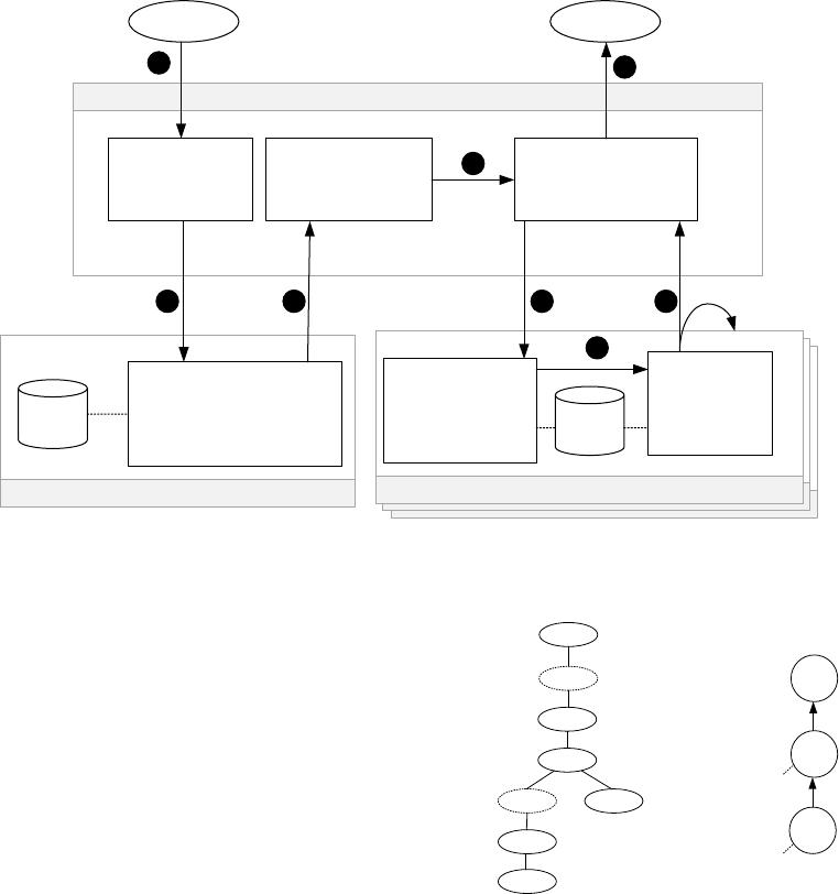
Unified ery Optimization in the Fabric Data Warehouse SIGMOD-Companion ’24, June 9–15, 2024, Santiago, AA, Chile
Backend SQL Server Engine(s)
Backend SQL Server Engine(s)
Backend SQL Server Engines (SQL BE)
Query Results
Frontend SQL Server (SQL FE)
Parser
Algebrizer
Optimizer (UQO)
Plan Generator
Shell DB
Execution
Wrapper
Cached DB
Execution
Engine
Polaris Distributed Compute Platform (DCP)
Workload Management
Task Scheduler
Distributed Query Processor (DQP)
1
2
3 4
5
6
Remote Storage
Backend SQL Server Engine(s)
Query Results
Frontend/Control SQL Server Engine
Parser
Algebrizer
Optimizer
Search Space Serializer
Shell
DB
Parser
Algebrizer
Optimizer
Plan Generator
Sharded
DB
Execution
Engine
PDW Distributed Engine
Parser
Validator
SQL Generator
Memo Parser
Optimizer (DQO)
D-Plan Generator
Scheduler
Executor
1
2 3
4
5
6
7
8
Figure 1: Life of a query in the original Parallel Data Warehouse system.
corresponds to a
SQL
template and edges represent data movement.
The SQL templates in the gure are dened as follows:
Q1: SELECT sa FROM S WHERE sb > 3
Q2: SELECT T.tb
FROM TempTable1 AS TT1 INNER JOIN T
ON TT1.sa = T.ta
GROUP BY T.tb
Q3: SELECT tb FROM TempTable2
GROUP BY tb
The distributed plan is evaluated one step at a time, by sending
the
SQL
fragments to the backend nodes, where they are optimized
and executed. First
𝑄
1 is sent and evaluated in multiple backend
nodes, reading fragments of table
𝑆
and ltering tuples that satisfy
𝑠𝑏 >
3. The result is estimated to be small enough that a replicated
join strategy is chosen, so the intermediate results are broadcast
to all nodes using
𝑇𝑒𝑚𝑝𝑇𝑎𝑏𝑙𝑒
1 as the backing store. Fragment
𝑄
2 is then sent to the backend nodes, where fragments of
𝑇
are
joined with the replicated
𝑇𝑒𝑚𝑝𝑇𝑎𝑏𝑙𝑒
1 and locally aggregated. The
results are then shued by the distinct column
𝑡𝑏
and stored in
𝑇𝑒𝑚𝑝𝑇𝑎𝑏𝑙𝑒
2. Finally, fragment
𝑄
3 is evaluated in all nodes, the
global distinct operator is applied to all fragments (since data is
partitioned by column
𝑇 .𝑡𝑏
) and results are sent back to the client.
3 LEARNINGS FROM PRODUCTION
Developing an industrial-strength query optimizer from scratch is a
major undertaking. Enumerating execution alternatives adequately
requires an understanding of relational algebra and its properties,
⨝
a=b
HashMove(a)
Scan T
GroupBy
b, c=sum(c)
HashMove(b)
GroupBy
b, c=count(*)
Scan S
⨝
a=b
Scan(Tmp
1
)
Scan T
GroupBy
b, c=sum(c)
GroupBy
b, c=count(*)
Scan S
Scan(Tmp
2
)
Hash(a) → Tmp
1
Hash(a) → Tmp
2
(a) Distributed plan (b) Distributed execution graph
Q3
Q2
Q1
T
S
Hash(tb) on
TempTable2
Broadcast on
TempTable1
GB
Tb
Hash(b)
LGB
Tb
⨝
Ta=Sa
Bcast
σ
Sb>3
S
T
(a) Distributed plan. (b) Distributed graph.
Figure 2: Distributed execution plan for a simple query.
as well as deriving and identifying desirable execution plans. Eec-
tive plan selection requires careful modeling of data distributions
and cost estimation and should go beyond simply parallelizing the
best serial plan. The PDW optimizer went beyond simple predi-
cate pushing and join reordering, and incorporated a number of
advanced query optimization techniques, including contradiction
detection, redundant join elimination, subquery unnesting, and
outerjoin reordering [20].
For a commercial product, time to market is a critical dimension
to consider. Rather than starting from scratch, the PDW query opti-
mizer reused technology developed for SQL Server, which has been
tuned and tested over a number of releases. This choice shortened
the time to build a cost-based optimizer for PDW and was an ef-
fective approach to quickly bring cost-based query optimization to
20
of 13
免费下载
【版权声明】本文为墨天轮用户原创内容,转载时必须标注文档的来源(墨天轮),文档链接,文档作者等基本信息,否则作者和墨天轮有权追究责任。如果您发现墨天轮中有涉嫌抄袭或者侵权的内容,欢迎发送邮件至:contact@modb.pro进行举报,并提供相关证据,一经查实,墨天轮将立刻删除相关内容。

相关文档
评论