


F1: A Distributed SQL Database That Scales.pdf
免费下载

F1: A Distributed SQL Database That Scales
Jeff Shute Radek Vingralek Bart Samwel Ben Handy
Chad Whipkey Eric Rollins Mircea Oancea Kyle Littlefield
David Menestrina Stephan Ellner John Cieslewicz Ian Rae*
Traian Stancescu Himani Apte
Google, Inc.
*University of Wisconsin-Madison
ABSTRACT
F1 is a distributed relational database system built at
Google to support the AdWords business. F1 is a hybrid
database that combines high availability, the scalability of
NoSQL systems like Bigtable, and the consistency and us-
ability of traditional SQL databases. F1 is built on Span-
ner, which provides synchronous cross-datacenter replica-
tion and strong consistency. Synchronous replication im-
plies higher commit latency, but we mitigate that latency
by using a hierarchical schema model with structured data
types and through smart application design. F1 also in-
cludes a fully functional distributed SQL query engine and
automatic change tracking and publishing.
1. INTRODUCTION
F1
1
is a fault-tolerant globally-distributed OLTP and
OLAP database built at Google as the new storage system
for Google’s AdWords system. It was designed to replace a
sharded MySQL implementation that was not able to meet
our growing scalability and reliability requirements.
The key goals of F1’s design are:
1. Scalability: The system must be able to scale up,
trivially and transparently, just by adding resources.
Our sharded database based on MySQL was hard to
scale up, and even more difficult to rebalance. Our
users needed complex queries and joins, which meant
they had to carefully shard their data, and resharding
data without breaking applications was challenging.
2. Availability: The system must never go down for any
reason – datacenter outages, planned maintenance,
schema changes, etc. The system stores data for
Google’s core business. Any downtime has a signifi-
cant revenue impact.
3. Consistency: The system must provide ACID trans-
actions, and must always present applications with
1
Previously described briefly in [22].
Permission to make digital or hard copies of all or part of this work for
personal or classroom use is granted without fee provided that copies are
not made or distributed for profit or commercial advantage and that copies
bear this notice and the full citation on the first page. To copy otherwise, to
republish, to post on servers or to redistribute to lists, requires prior specific
permission and/or a fee. Articles from this volume were invited to present
their results at The 39th International Conference on Very Large Data Bases,
August 26th - 30th 2013, Riva del Garda, Trento, Italy.
Proceedings of the VLDB Endowment, Vol. 6, No. 11
Copyright 2013 VLDB Endowment 2150-8097/13/09... 10.00.
consistent and correct data.
Designing applications to cope with concurrency
anomalies in their data is very error-prone, time-
consuming, and ultimately not worth the performance
gains.
4. Usability: The system must provide full SQL query
support and other functionality users expect from a
SQL database. Features like indexes and ad hoc query
are not just nice to have, but absolute requirements
for our business.
Recent publications have suggested that these design goals
are mutually exclusive [5, 11, 23]. A key contribution of this
paper is to show how we achieved all of these goals in F1’s
design, and where we made trade-offs and sacrifices. The
name F1 comes from genetics, where a Filial 1 hybrid is the
first generation offspring resulting from a cross mating of
distinctly different parental types. The F1 database system
is indeed such a hybrid, combining the best aspects of tradi-
tional relational databases and scalable NoSQL systems like
Bigtable [6].
F1 is built on top of Spanner [7], which provides extremely
scalable data storage, synchronous replication, and strong
consistency and ordering properties. F1 inherits those fea-
tures from Spanner and adds several more:
• Distributed SQL queries, including joining data from
external data sources
• Transactionally consistent secondary indexes
• Asynchronous schema changes including database re-
organizations
• Optimistic transactions
• Automatic change history recording and publishing
Our design choices in F1 result in higher latency for typi-
cal reads and writes. We have developed techniques to hide
that increased latency, and we found that user-facing trans-
actions can be made to perform as well as in our previous
MySQL system:
• An F1 schema makes data clustering explicit, using ta-
bles with hierarchical relationships and columns with
structured data types. This clustering improves data
locality and reduces the number and cost of RPCs re-
quired to read remote data.
• F1 users make heavy use of batching, parallelism and
asynchronous reads. We use a new ORM (object-
relational mapping) library that makes these concepts
explicit. This places an upper bound on the number of
RPCs required for typical application-level operations,
making those operations scale well by default.
The F1 system has been managing all AdWords advertis-
ing campaign data in production since early 2012. AdWords
is a vast and diverse ecosystem including 100s of applica-
tions and 1000s of users, all sharing the same database. This
database is over 100 TB, serves up to hundreds of thousands
of requests per second, and runs SQL queries that scan tens
of trillions of data rows per day. Availability reaches five
nines, even in the presence of unplanned outages, and ob-
servable latency on our web applications has not increased
compared to the old MySQL system.
We discuss the AdWords F1 database throughout this pa-
per as it was the original and motivating user for F1. Several
other groups at Google are now beginning to deploy F1.
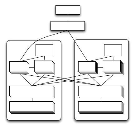
2. BASIC ARCHITECTURE
Users interact with F1 through the F1 client library.
Other tools like the command-line ad-hoc SQL shell are im-
plemented using the same client. The client sends requests
to one of many F1 servers, which are responsible for reading
and writing data from remote data sources and coordinating
query execution. Figure 1 depicts the basic architecture and
the communication between components.
F1 Client
Load Balancer
...
Spanner
CFS
F1
Server
Slave
Pool
Slave
Pool
Spanner
CFS
F1
Server
Slave
Pool
Slave
Pool
F1
Master
F1
Master
Figure 1: The basic architecture of the F1 system,
with servers in two datacenters.
Because of F1’s distributed architecture, special care must
be taken to avoid unnecessarily increasing request latency.
For example, the F1 client and load balancer prefer to con-
nect to an F1 server in a nearby datacenter whenever possi-
ble. However, requests may transparently go to F1 servers
in remote datacenters in cases of high load or failures.
F1 servers are typically co-located in the same set of dat-
acenters as the Spanner servers storing the data. This co-
location ensures that F1 servers generally have fast access
to the underlying data. For availability and load balancing,
F1 servers can communicate with Spanner servers outside
their own datacenter when necessary. The Spanner servers
in each datacenter in turn retrieve their data from the Colos-
sus File System (CFS) [14] in the same datacenter. Unlike
Spanner, CFS is not a globally replicated service and there-
fore Spanner servers will never communicate with remote
CFS instances.
F1 servers are mostly stateless, allowing a client to com-
municate with a different F1 server for each request. The
one exception is when a client uses pessimistic transactions
and must hold locks. The client is then bound to one F1
server for the duration of that transaction. F1 transactions
are described in more detail in Section 5. F1 servers can
be quickly added (or removed) from our system in response
to the total load because F1 servers do not own any data
and hence a server addition (or removal) requires no data
movement.
An F1 cluster has several additional components that
allow for the execution of distributed SQL queries. Dis-
tributed execution is chosen over centralized execution when
the query planner estimates that increased parallelism will
reduce query processing latency. The shared slave pool con-
sists of F1 processes that exist only to execute parts of dis-
tributed query plans on behalf of regular F1 servers. Slave
pool membership is maintained by the F1 master, which
monitors slave process health and distributes the list of avail-
able slaves to F1 servers. F1 also supports large-scale data
processing through Google’s MapReduce framework [10].
For performance reasons, MapReduce workers are allowed to
communicate directly with Spanner servers to extract data
in bulk (not shown in the figure). Other clients perform
reads and writes exclusively through F1 servers.
The throughput of the entire system can be scaled up by
adding more Spanner servers, F1 servers, or F1 slaves. Since
F1 servers do not store data, adding new servers does not
involve any data re-distribution costs. Adding new Spanner
servers results in data re-distribution. This process is com-
pletely transparent to F1 servers (and therefore F1 clients).
The Spanner-based remote storage model and our geo-
graphically distributed deployment leads to latency char-
acteristics that are very different from those of regu-
lar databases. Because the data is synchronously repli-
cated across multiple datacenters, and because we’ve cho-
sen widely distributed datacenters, the commit latencies are
relatively high (50-150 ms). This high latency necessitates
changes to the patterns that clients use when interacting
with the database. We describe these changes in Section 7.1,
and we provide further detail on our deployment choices, and
the resulting availability and latency, in Sections 9 and 10.
2.1 Spanner
F1 is built on top of Spanner. Both systems were devel-
oped at the same time and in close collaboration. Spanner
handles lower-level storage issues like persistence, caching,
replication, fault tolerance, data sharding and movement,
location lookups, and transactions.
In Spanner, data rows are partitioned into clusters called
directories using ancestry relationships in the schema. Each
directory has at least one fragment, and large directories
can have multiple fragments. Groups store a collection of
directory fragments. Each group typically has one replica
tablet per datacenter. Data is replicated synchronously using
the Paxos algorithm [18], and all tablets for a group store
the same data. One replica tablet is elected as the Paxos
leader for the group, and that leader is the entry point for
all transactional activity for the group. Groups may also
include readonly replicas, which do not vote in the Paxos
algorithm and cannot become the group leader.
Spanner provides serializable pessimistic transactions us-
ing strict two-phase locking. A transaction includes mul-
tiple reads, taking shared or exclusive locks, followed by a
single write that upgrades locks and atomically commits the
transaction. All commits are synchronously replicated us-
ing Paxos. Transactions are most efficient when updating
data co-located in a single group. Spanner also supports
transactions across multiple groups, called transaction par-
ticipants, using a two-phase commit (2PC) protocol on top
of Paxos. 2PC adds an extra network round trip so it usu-
ally doubles observed commit latency. 2PC scales well up to
10s of participants, but abort frequency and latency increase
significantly with 100s of participants [7].
Spanner has very strong consistency and timestamp se-
mantics. Every transaction is assigned a commit timestamp,
and these timestamps provide a global total ordering for
commits. Spanner uses a novel mechanism to pick glob-
ally ordered timestamps in a scalable way using hardware
clocks deployed in Google datacenters. Spanner uses these
timestamps to provide multi-versioned consistent reads, in-
cluding snapshot reads of current data, without taking
read locks. For guaranteed non-blocking, globally consis-
tent reads, Spanner provides a global safe timestamp, below
which no in-flight or future transaction can possibly com-
mit. The global safe timestamp typically lags current time
by 5-10 seconds. Reads at this timestamp can normally run
on any replica tablet, including readonly replicas, and they
never block behind running transactions.
3. DATA MODEL
3.1 Hierarchical Schema
The F1 data model is very similar to the Spanner data
model. In fact, Spanner’s original data model was more like
Bigtable, but Spanner later adopted F1’s data model. At
the logical level, F1 has a relational schema similar to that
of a traditional RDBMS, with some extensions including
explicit table hierarchy and columns with Protocol Buffer
data types.
Logically, tables in the F1 schema can be organized into
a hierarchy. Physically, F1 stores each child table clustered
with and interleaved within the rows from its parent table.
Tables from the logical schema cannot be arbitrarily inter-
leaved: the child table must have a foreign key to its parent
table as a prefix of its primary key. For example, the Ad-
Words schema contains a table Customer with primary key
(CustomerId), which has a child table Campaign with pri-
mary key (CustomerId, CampaignId), which in turn has
a child table AdGroup with primary key (CustomerId,
CampaignId, AdGroupId). A row of the root table in the
hierarchy is called a root row. All child table rows corre-
sponding to a root row are clustered together with that root
row in a single Spanner directory, meaning that cluster is
normally stored on a single Spanner server. Child rows are
stored under their parent row ordered by primary key. Fig-
ure 2 shows an example.
The hierarchically clustered physical schema has several
advantages over a flat relational schema. Consider the cor-
responding traditional schema, also depicted in Figure 2. In
this traditional schema, fetching all Campaign and AdGroup
records corresponding to a given CustomerId would take two
sequential steps, because there is no direct way to retrieve
AdGroup records by CustomerId. In the F1 version of the
schema, the hierarchical primary keys allow the fetches of
Campaign and AdGroup records to be started in parallel,
because both tables are keyed by CustomerId. The primary
key prefix property means that reading all AdGroups for
a particular Customer can be expressed as a single range
read, rather than reading each row individually using an
index. Furthermore, because the tables are both stored in
primary key order, rows from the two tables can be joined
using a simple ordered merge. Because the data is clustered
into a single directory, we can read it all in a single Spanner
request. All of these properties of a hierarchical schema help
mitigate the latency effects of having remote data.
Hierarchical clustering is especially useful for updates,
since it reduces the number of Spanner groups involved in
a transaction. Because each root row and all of its descen-
dant rows are stored in a single Spanner directory, trans-
actions restricted to a single root will usually avoid 2PC
and the associated latency penalty, so most applications try
to use single-root transactions as much as possible. Even
when doing transactions across multiple roots, it is impor-
tant to limit the number of roots involved because adding
more participants generally increases latency and decreases
the likelihood of a successful commit.
Hierarchical clustering is not mandatory in F1. An F1
schema often has several root tables, and in fact, a com-
pletely flat MySQL-style schema is still possible. Using hi-
erarchy however, to the extent that it matches data seman-
tics, is highly beneficial. In AdWords, most transactions are
typically updating data for a single advertiser at a time, so
we made the advertiser a root table (Customer) and clus-
tered related tables under it. This clustering was critical to
achieving acceptable latency.
3.2 Protocol Buffers
The F1 data model supports table columns that con-
tain structured data types. These structured types use the
schema and binary encoding format provided by Google’s
open source Protocol Buffer [16] library. Protocol Buffers
have typed fields that can be required, optional, or repeated;
fields can also be nested Protocol Buffers. At Google, Proto-
col Buffers are ubiquitous for data storage and interchange
between applications. When we still had a MySQL schema,
users often had to write tedious and error-prone transfor-
mations between database rows and in-memory data struc-
tures. Putting protocol buffers in the schema removes this
impedance mismatch and gives users a universal data struc-
ture they can use both in the database and in application
code.
Protocol Buffers allow the use of repeated fields. In F1
schema designs, we often use repeated fields instead of child
tables when the number of child records has a low upper
bound. By using repeated fields, we avoid the performance
overhead and complexity of storing and joining multiple
child records. The entire protocol buffer is effectively treated
as one blob by Spanner. Aside from performance impacts,
Protocol Buffer columns are more natural and reduce seman-
tic complexity for users, who can now read and write their
logical business objects as atomic units, without having to
of 12
免费下载
【版权声明】本文为墨天轮用户原创内容,转载时必须标注文档的来源(墨天轮),文档链接,文档作者等基本信息,否则作者和墨天轮有权追究责任。如果您发现墨天轮中有涉嫌抄袭或者侵权的内容,欢迎发送邮件至:contact@modb.pro进行举报,并提供相关证据,一经查实,墨天轮将立刻删除相关内容。
最新上传

文档被以下合辑收录
相关文档
评论